 Futurewood
- >
- Products
- >
- Fixing Guidelines
Fixing Guidelines
Fixing & Handling
- CleverDeck Original/Eco-Pro
- CleverDeck Xtreme
- EnviroSlat Decorative Cladding and Screening
- EnviroSlat Weatherproof Cladding
- Aluminium Deck Frame System
CleverDeck® Original/Eco-Pro
Composite decking has unique characteristics and requires specific fixing requirements that differ from timber.
Storage
CleverDeck Original/Eco-Pro composite timber decking must be stored flat and dry and off the ground. Standard 5.4 metre long packs of CleverDeck Original/Eco-Pro decking require a minimum of seven gluts (supports) under the pack for proper storage.
Take care when handling CleverDeck Original/Eco-Pro decking as the boards are finished and ready to use and rough handling might cause visible scratches and marks on the deck boards.
Safety and Tools
As with any building project you should ensure that the correct tools and proper protective equipment are being used. It is the responsibility of the user to follow safe practices when using any tools during the installation process. Remember that CleverDeck Original/Eco-Pro composite timber decking is heavier than most traditional timbers and should be lifted and carried with care.
CleverDeck Original/Eco-Pro composite timber decking can be drilled, cut, fastened or routed with normal woodworking tools.
In order to maintain clean cutting of the deck boards Futurewood recommends using a minimum 20 tooth carbide tipped saw blade. All other cutting tools should be carbide tipped and kept sharp.
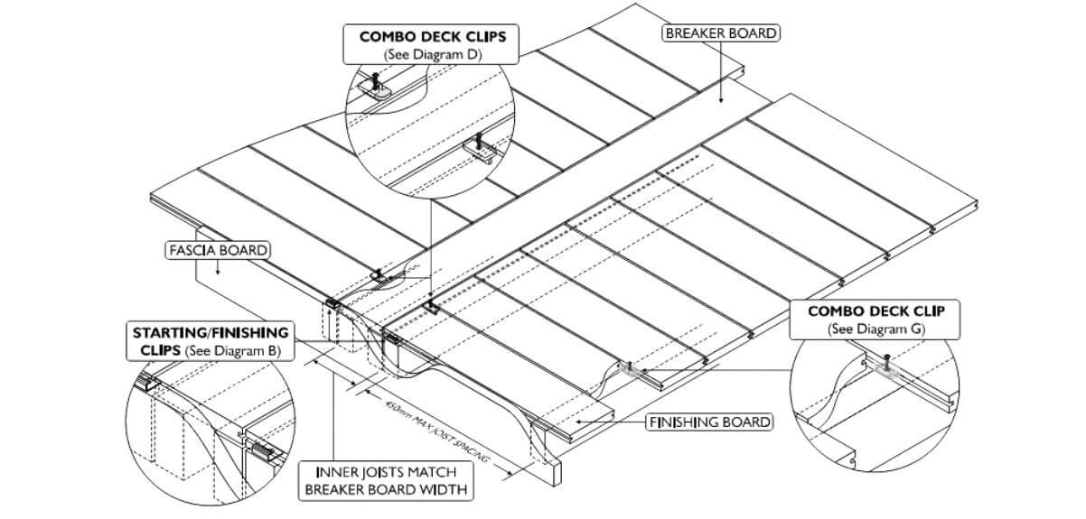
Foundation, Sub-structure & Coverage (Refer diagram A)
CleverDeck Original/Eco-Pro composite timber decking cannot be used as a component of the foundation or substructure.
When constructing the substructure care must be taken to ensure that the joists are level, straight and square as CleverDeck Original/Eco-Pro composite timber decking will conform to the level and orientation of the joists.
An appropriate allowance for fall per metre of deck must be made when constructing the deck substructure. The deck should fall away from the structure. There must be enough fall on the boards so that any water that falls on the deck can run-off. If the fall is insufficient to allow run-off then water puddling will most likely occur and water puddling will cause water staining particularly when the boards are new.
Boards fixed across the deck at angles other than 90 degrees to the joists require closer joist spacing. Check the fixings specifications table on page 13 to make sure that you have the correct spacing between the joists. As a rule, the closer the joists the better the deck.
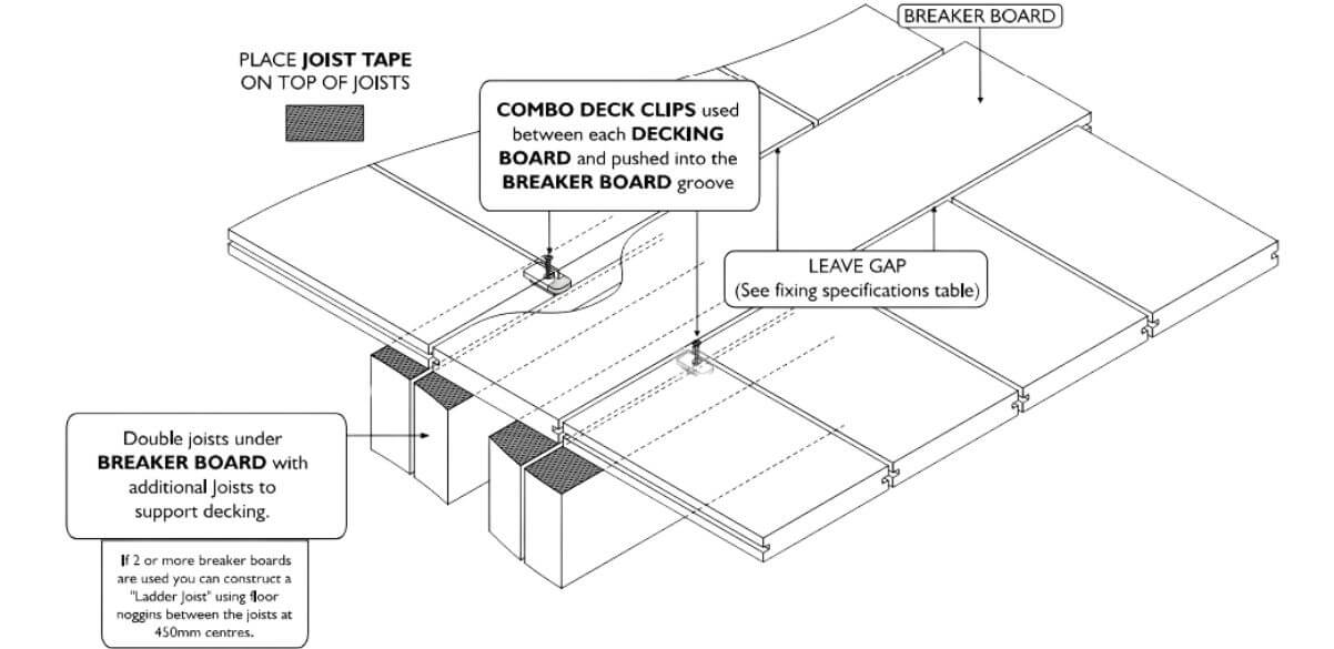
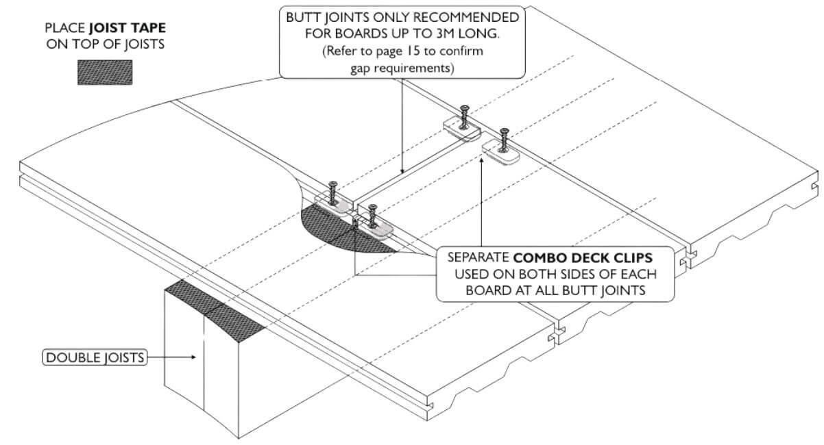
Futurewood recommends the use of a good quality self-adhesive joist protection tape to protect the timber joists under your deck boards. The joist tape will ensure that the top of the joists remain dry and it stops any water/moisture from sitting between the bottom of the deck board and the joist improving the overall quality of your deck installation and reducing the risk of your joists rotting prematurely.
The 138mm wide CleverDeck Original/Eco-Pro composite timber decking board combined with the Futurewood Combo Deck Clip provides a cover of 144mm or 7 boards per lineal metre.
Additional joists will be required where breaker boards are used in the deck design. Read through the section below referring to breaker boards and determine your deck design before you calculate how many joists will be required for the deck.
The decking boards can overhang the sub frame by up to 50mm in length. The decking boards can overhang the subfame by 10mm in width or a combination of the subframe and fascia board by 10mm in width if the fascia board is level with the joists. Consideration should be given to the overall deck size and the number of boards required to cover the deck.
You can start from the inner or outer edge of the deck depending on whether you are using full boards or whether you need to cut the board which is normally against a wall of an existing structure. The deck boards will be installed across the deck and the last board (finishing board) may need to be trimmed in order to fit in the space against the house or structure. Due to normal manufacturing tolerances and the potential for a slight difference in spacing between deck boards we do not recommend trying to pre-determine the width of the final board (the outer board must finish flush or no more than 10mm in width past the joist or fascia board). Any cut outs around protrusions such as a verandah posts or balustrades need to be fully supported.
Butt joins should only occur over a double joist. (Only recommended for boards up to 3 metres long)
CleverDeck Original/Eco-Pro composite timber decking should not be attached directly to any solid surface or watertight flooring system, such as concrete, brick or tiled patios, waterproof membranes or roofing. If fixing over concrete the decking board can be fixed directly to a batten that is in contact with the concrete. A minimum 25mm batten is required. When fixing over concrete it is critical that no water is allowed to pool under the deck. Good drainage under the deck is essential and the joists should ideally run in the direction of the fall of the concrete. If the joists need to run across the fall of the concrete then they should be raised or checked out accordingly so that water will not pool behind them.
Ventilation is a necessary requirement under and around your CleverDeck Original/Eco-Pro decking boards. The Futurewood Combo Deck Clips provide a 6mm gap between each CleverDeck Original/Eco-Pro composite timber decking board. 300mm clearance is an ideal distance between the boards and any permeable surface beneath the deck however the minimum ground clearance required is 100mm. Do not completely seal off deck ends to allow some air-flow under the deck, any water must be able to drain away freely.
The area under the deck should be dry and clear of vegetation. Drainage will be required if the ground below the deck typically holds water.
Diagram A
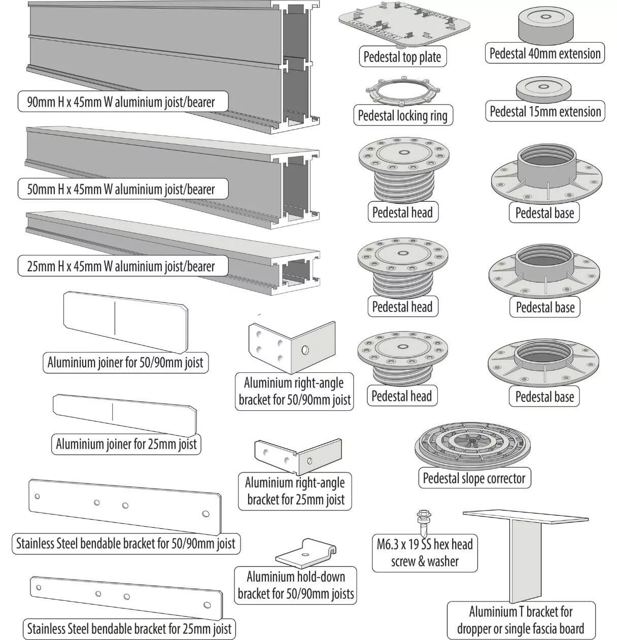
Adjustable Pedestal & Aluminium Joist Subframe System – Design Registered
Futurewood has a range of aluminium joists and variable height pedestals along with quick fix brackets and clips to allow you the option of constructing a rot proof subframe to support your CleverDeck Composite Timber Decking.
With joist heights of 25mm, 50mm and 90mm you can span between 600mm and 1800mm using individual joists or joist and bearer combinations depending on your deck height and the surface that the deck is being installed over.
The adjustable pedestal range covers heights from 14mm to 320mm. This range of pedestal sizes combined with a joist or joist/bearer combination and a CleverDeck composite timber decking board allow you to build your deck across a range of heights from 48mm to 523mm. For higher decks, we recommend using a reblocking concrete stump instead of our adjustable height pedestals.
The aluminium joist and bearers use a range of quick fix clips, brackets and screws. The special registered design of the joists and brackets allows for different fixing options that require only 1 screw per bracket/clip meaning that there is less labour required to produce a perfectly level and square subframe using straight lengths of lightweight aluminium.
All components have been tested for both residential and commercial loadings.
The low height pedestals and the 25mm high joist can be used together on concrete or tiled patios/balconies where there is insufficient height to use a traditional stump, bearer and joist subframe.
The full range of pedestals and aluminium joists/bearers that make up the subframe can also be installed using traditional concrete pads positioned, in the ground, in an appropriate grid pattern for the span of the joist/bearer.
A detailed drawing of the subframe can be supplied for each installation where required.
Failure to correctly install your CleverDeck Original/Eco-Pro composite timber decking may void your warranty.
Colour and Orientation
The natural fibres used in the manufacture of CleverDeck Original/Eco-Pro composite timber decking allow some colour variation between boards and will enable the overall colour to lighten, creating a weathered colour effect over time. Allow 8-12 weeks of full exposure to sunlight for most of the colour weathering to occur.
The grain of CleverDeck Original/Eco-Pro composite timber decking will reflect light differently depending on the orientation of the boards. To ensure the same look across the deck it is necessary to run all deck boards in the same grain direction.
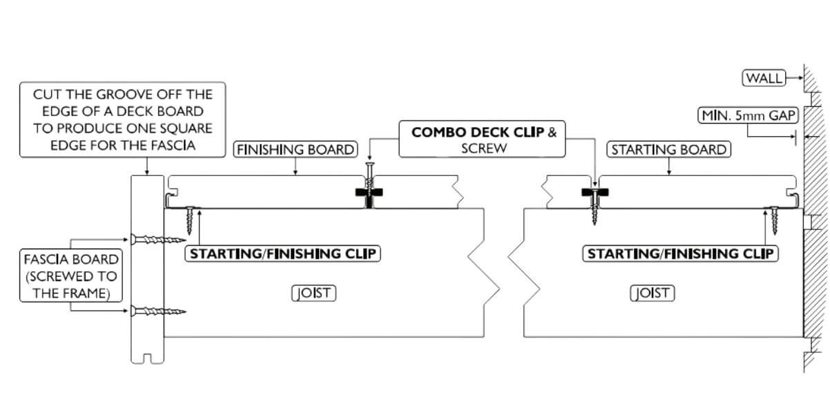
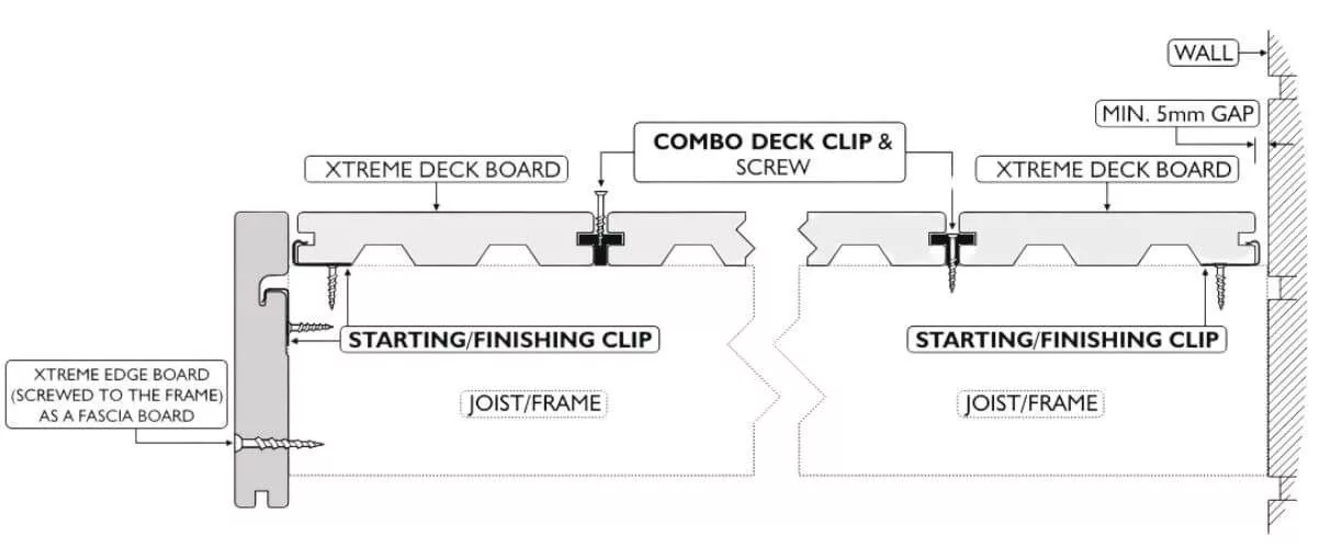
Starting, Finishing & Fascia Boards (Refer diagram B)
The first board laid on your deck is referred to as the starting board and will normally be installed with one “free” edge typically gapped against the side of a wall/structure or at the outside edge of the deck.
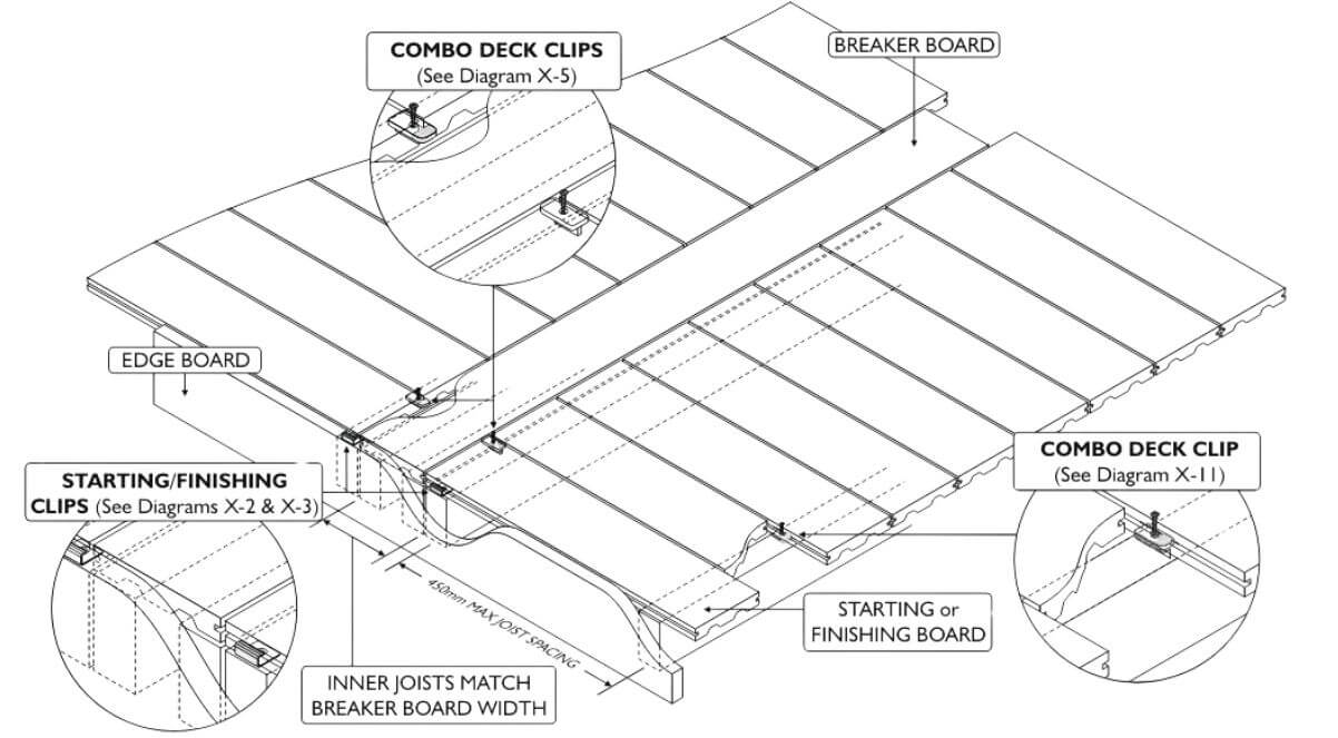
As the starting board can only be fixed with the Futurewood Combo deck clip on the back edge of the board you need to use the Futurewood Starting/finishing (S/f) clip to secure the outer edge of the starting board. The S/f clip should be positioned close to the outer edge of the deck joists at 900mm intervals (every 2nd joist) so that the fascia board can be fitted flush against the ends of the joists/subframe. fix the S/f clips to the joists then push the starting board in to the clip at a slight angle (about 30 degrees) so that the clip engages fully in the groove.
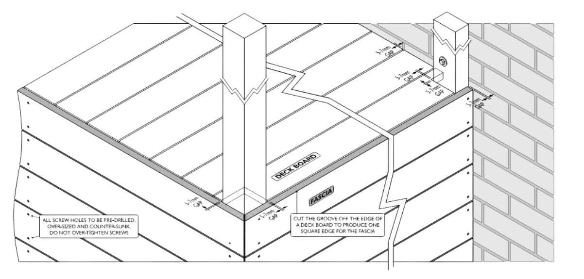
If the outer edge of the deck is going to be visible and you do not want to see the S/f clip or the groove on the edge of the first board then you can use one of the deck boards as a fascia board and remove the groove with a saw or use a square edged EnviroSlat board and position this level with the height of the deck boards to hide the S/f clip and the groove in the outer edge of the starting deck board (as shown in diagram b).
Before screwing down the Combo deck clips on the back edge of your starting board make sure that you place your next (second) deck board over the deck clips so that both edges of the deck clip are concealed (inside the groove on the back edge of the starting board and the front edge of the second board).
The finishing or last board should be treated in the same way as the starting board. The width of the finishing board can be reduced as required by sawing so that it can fit in between the adjacent structure and the 2nd last board or if you have a free standing deck so that it does not overhang the joists or fascia board by more than 10mm. Grooves can be cut in to the board edge at 900mm intervals (every 2nd joist) using a router or biscuit cutter to allow starting or finishing clips to be used on the cut board edge. CleverDeck Original/Eco-Pro composite timber decking boards make ideal fascia boards. If the cut section of the finishing board is less than 100mm in width we recommend using noggins between each joist to fully support the cut width board along its length.
When using CleverDeck Original/Eco-Pro composite timber decking boards as fascia boards they should be screwed (pre-drill and pre- countersink all screws) at a maximum of 900mm centres to an appropriate frame fixed to the sub frame.
When using the CleverDeck Original/Eco-Pro composite timber decking board as a fascia board the groove can be removed as required.
Diagram B
Breaker Boards & “Border OR Picture Frame Boards” (Refer diagrams C and D)
A breaker board is a regular deck board that is positioned in your deck design at 90 degrees to the main deck boards to provide the necessary gap for expansion and contraction between the ends of deck boards (refer to the table on page 12 for correct gapping).
Wherever a breaker board is positioned it must be supported by a minimum of 2 – 90mm x 45mm joists and the ends of the boards butting up to either side of the breaker board need to finish on a full joist meaning that 4 standard 45mm wide joists are required to adequately support a breaker board. If multiple breaker boards are being used a ladder joist or noggins between joists can be used to fully support all the breaker boards at a maximum of 450mm centres.
A picture frame board or border will need 2 joists to support it and 1 joist to support the deck boards that run up to the picture frame board. Due to the expansion and contraction of the boards, a picture frame or border should not exceed 3 metres in length if it is to be butt joined.
Running long boards with a butt join may result in a gap of more than 10mm once the boards have cooled and contracted. If staggered butt joins are to be used, we recommend that you contact futurewood to discuss your specific fixing options.
Breaker boards should be fixed using the Combo deck clip. The combo deck clips that are positioned at the end of each deck board, can be slid out past the end of the deck board so that the nose of the clip engages in the groove of the breaker board.
Because CleverDeck Original/Eco-Pro composite timber decking comes in standard 5.4 metre long lengths the preferred method of installation is to use a breaker board rather than having randomly spaced butt joins spread across the deck. Depending on your overall deck size/shape you may need to allow for the inclusion of one or more breaker boards in the design of your deck. The incorporation of the breaker board can greatly enhance the character and appearance of your deck as well as allowing you to use potential off cuts (helping to minimise overall board wastage). Additional joists will be required in your sub floor construction to fully support the breaker boards wherever they are being used.
The breaker boards should be left loose and placed in between the regular deck boards then the breaker board can be evenly spaced between either side of the regular deck boards and the Combo Deck Clips can be pushed against the breaker board so that the nose of the clip engages in the groove of the breaker board before driving home the screws.
We recommend that any breaker boards, whether they are butted together or are a single board, do not exceed 3 metres in length (e.g. a 5.4 metre board would be cut in half producing 2 x 2.7 metre boards). The butt joins between these boards should be gapped according to the table on page 13. This will help to minimise the potential for an excessive gap developing at the butt join between the breaker boards or for a single longer breaker board to expand beyond the side of the deck.
Diagram C
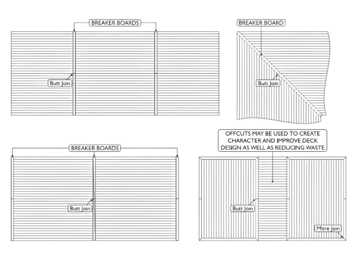
Diagram D
Stairs (Refer diagram E and F)
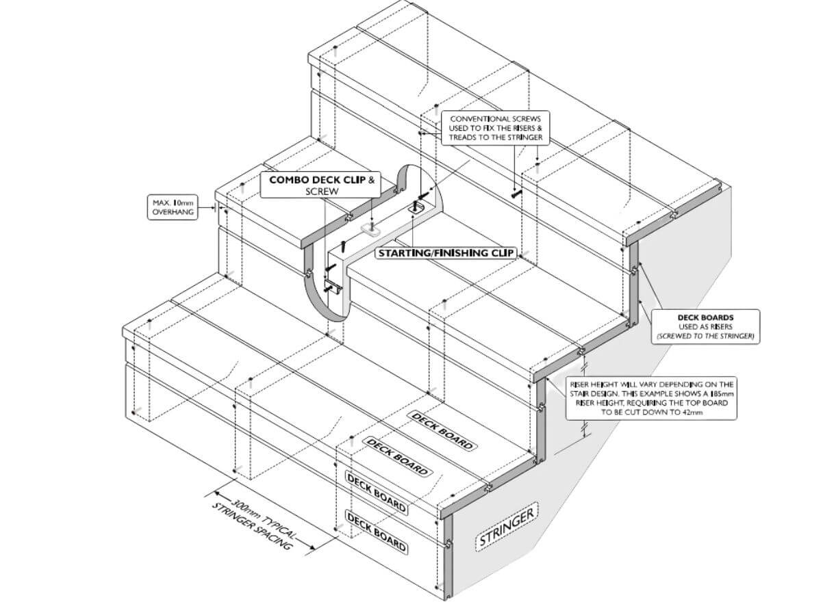
CleverDeck Original/Eco-Pro composite timber decking boards can be used as stair treads and for stair risers. When using CleverDeck Original/Eco-Pro composite timber decking boards for stair treads they must be supported at a maximum of 300mm centres by a stair stringer or other structural support. A typical stair tread or riser will normally require more than one CleverDeck Original/Eco-Pro 138mm wide composite timber decking board to make up the minimum required stair tread width or riser height. The final total stair tread width or riser height might require one or more of the CleverDeck Original/Eco-Pro composite timber decking boards to be cut to reduce the overall width or height of that board. The solid CleverDeck Original/Eco-Pro composite timber decking boards can be easily cut along their width and the cut edge sanded or finished as required. There are several different ways that stairs can be built, with or without risers and with stair treads overhanging or flush. CleverDeck Original/Eco-Pro composite timber decking boards can be used in all examples, but the fixing methods vary and using concealed fixing is not possible for all installation methods.
In some cases, CleverDeck Original/Eco-Pro composite timber decking boards will need to be fixed as stair treads or risers by screwing through the face of the board. note: all holes must be pre-drilled and pre-countersunk to ensure a neat finish and not risk damaging the boards.
When 2 full width boards are being used for the stair tread Combo Deck Clips can be used between the boards and Starting/Finishing Clips can be used at the back edge of the stair tread if they are hidden at the back/underside of the stairs or if the riser comes down against the back of the stair tread or on top of it. The front edge of the front board can be fixed with starting/finishing clips if the stair riser is finishing flush with the stair tread on the outside of the deck board.
If the front stair tread has an exposed edge and is mounted over the top of, but flush with the riser, the grooved edge can be cut off and the solid edge routered or sanded to produce a square edge. For this type of installation, the front edge of the front stair tread will need to be screwed to the stringers.
If the front stair tread has an exposed edge and is overhanging the riser (the maximum overhang is 10mm) the grooved edge can be cut off and the solid edge routered or sanded to produce a rounded edge. for this type of installation, the front edge of the front stair tread will need to be screwed to the stringers.
If stair risers are included in the stair design, it might be possible to use a concealed fix starting/finishing clip on one edge, but it is most likely that face fixing the riser by screwing through a pre-drilled and pre-countersunk hole will be necessary to fully fix the riser.
Diagram E
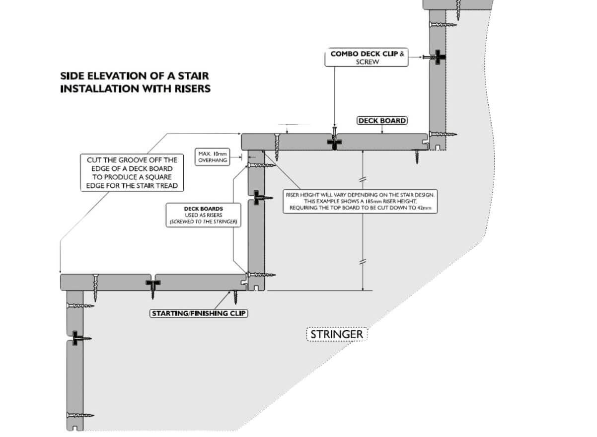
Diagram F
Fastening
Futurewood Deck Clip System (Refer diagram G)
The Futurewood Deck Clip System has been specifically designed for fixing CleverDeck composite timber decking boards and provides the added value and appearance of a concealed fix while saving time and money on the installation of the deck. It is highly recommended to use Futurewood Deck Clips & screws when installing CleverDeck composite timber decking.
Futurewood Combo Deck Clips and Locking Clips are supplied with blackened stainless-steel screws for fixing to either timber or metal joists. These screws have specially made, smaller screw heads to fit between the decking boards and are made with a T15 drive. T15 drives are supplied with these clips/screws. Starting/Finishing Clips come with stainless-steel screws for timber joists or stainless-steel pop rivets for fixing to metal joists and BAL clips are supplied without screws.
Make sure that you specify the correct clips based on the table below;
Note: Screws for self-drilling into metal are designed to cut through soft/mild hardness metal to a maximum thickness of 1.6 mm. harder/thicker metals will need to be pre-drilled.
| Part Number | Quantity per pack/box | Type | Screws for Joist Type | Coverage based on 450mm joist |
|---|---|---|---|---|
|
M-100 
|
100 | Combo deck clips c/w 410 S/S screw + 2 -T15 drivers | Metal | 138mm wide decking 6 square metres 185mm decking 8 square metres |
|
T-100
|
100 | Combo deck clips c/w 316 S/S screw + 2 -T15 drivers | Timber | 138mm wide decking 6 square metres 185mm decking 8 square metres |
|
SFM-20 
|
20 | 304 S/S starting/finishing clips c/w 304 S/S pop rivet | Metal | 3 x 5.4 metre deck boards |
|
SFT-20
|
20 | 304 S/S starting/finishing clips c/w 304 S/S screw | Timber | 3 x 5.4 metre deck boards |
|
LM-20 
|
20 | 316 S/S locking clips c/w 410 S/S screw + 1 -T15 driver | Metal | 20 boards regardless of length |
|
LT-20
|
20 | 316 S/S locking clips c/w 316 S/S screw + 1 -T15 driver | Timber | 20 boards regardless of length |
|
BAL-100 
|
100 | 304 S/S BAL 2mm gap deck clips – no screw | Metal/Timber | 138mm wide decking 5.8 square metres 185mm decking 7.8 square metres |
Futurewood Combo Deck Clips should be used at each joist regardless of joist spacing.
Locking Clips are used to stop the individual deck boards from creeping in one direction or the other even though they are fixed with the Combo Deck Clips. The Locking Clip will help to prevent the board from creeping or “walking” along the deck. This creeping or “walking” can occur due to the continual expansion and contraction of CleverDeck Original/Eco-Pro composite timber decking boards with changing temperatures.
One Locking Clip should be used in place of the Combo Deck Clip on either side of every board, at the joist that is closest to the centre of each board, regardless of board length.
Note: The Locking Clip will not work if it is not positioned close to the centre of the board.
Combo Deck Clips should be loosely positioned in the groove of the deck board over each joist as well as one Locking Clip over the joist that is closest to the centre of the board before sliding the next board into position. Once the starter board is aligned and fixed in position you can prepare up to 7 boards pushed together with the clips in position over each joist. Apply enough force against the last board you are fixing in the “set” so that the boards are pushed close together (you can use a string line to ensure that the boards are straight and true) and then fix the set in place by screwing down the clips on the inside of the outer board (the last row of clips that have a board on either side of them). Make sure that all clips are evenly spaced over the joists before fixing them. Once the outer board is secure, you can screw down all the clips between the other boards (you may want to leave these clips unfastened until all the boards have been positioned on the deck just in case any last-minute adjustments to any boards are required). Repeat this process until you reach the finishing board.
Combo Deck Clips are used to secure any breaker boards that are part of the deck design (refer to the breaker board section on pages 4 and 5).
Starting/Finishing Board Clips are used on the first and last board on the deck (refer to the Starting Boards section on page 4).
The BAL is a special clip designed to give a 2-3mm gap between boards as required in a high bush fire zone. Contact Futurewood for more information.
Diagram G
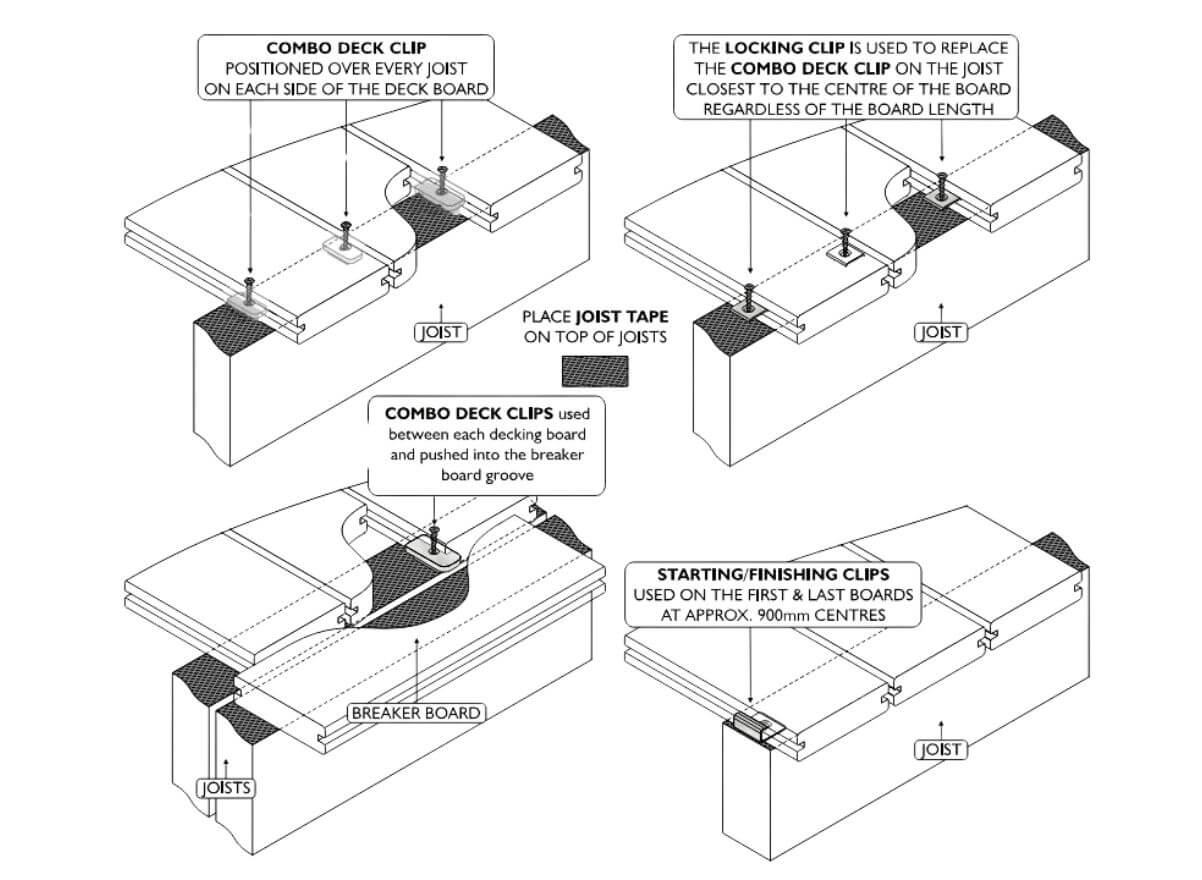
Diagram H
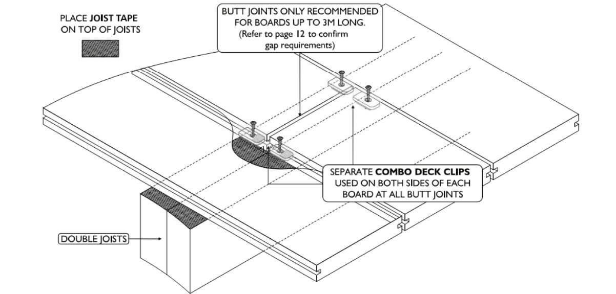
When fixing a butt joint use a Combo Deck Clip on both sides of each deck board (4 in total for each butt join, refer diagram H).
Drivers should be adjusted to a low or medium torque setting when fixing all Futurewood Deck Clips to ensure that the screws are not “over driven” into the clips.
Additional care must be taken when fixing Combo Deck Clips to steel joists to ensure the screws cut properly and to reduce the risk of the driver or screw head stripping. If the screw does not self drill, the metal may be too hard or too thick and will need to be pre-drilled.
We recommend that a slow speed and minimal force is used to drive the screw through the clip until it is touching the steel. At this point the speed of the driver should be increased to approximately 1000rpm to allow the cutting edge on the screw to cut through the steel. Too much pressure or too little speed may cause the screw to go off line and will strip out the screw head and or the driver. Once the screw has cut through the steel, any pressure on the driver should be reduced immediately to stop the screw from driving through the clip.
Combo Deck Clips provide an automatic spacing of 6mm (+/- manufacturing tolerances) between each board.
The Futurewood Deck Clip System provides the best fixing option for CleverDeck Original/Eco-Pro composite timber decking as the clips are designed to allow the decking to “work” with the deck clip maintaining independent expansion and contraction between the decking boards and the joists. This independent fixing method virtually eliminates the pressure build up on the fastenings that can occur when the decking is fastened directly to joists.
Screw Fixing
Screw fixing is generally not needed or recommended other than for some stair installations where short boards are used, however, if there is a need to screw fix some boards on your deck please note the following instructions.
Pre-drilling and pre-countersinking are essential in order to reduce the risk of splitting when screwing directly into the face of the CleverDeck Original/Eco-Pro composite timber decking. A minimum screw length of 60mm is required. When fixing a butt joint two screws are required to be positioned 25mm from the outside edge of each board and a minimum of 25mm from the end of each board. Drivers should be adjusted to a low or medium torque setting when fixing screws into CleverDeck Original/Eco-Pro composite timber decking. Screws should not be “over driven or over tightened” into the decking.
Screw fixing directly through the CleverDeck Original/Eco-Pro composite timber decking board is not recommended on steel joists when the board length is over 3 metres due to the different expansion and contraction characteristics of the two materials.
Nail Fixing
Nailing is not recommended.
Spacing (Refer diagram I)
CleverDeck Original/Eco-Pro composite timber decking expands and contracts lengthways due to changes in temperature (there is minimal change to the width of the board). It is critical that you have all the boards at roughly the same temperature and below 30°C as boards cut at different temperatures will affect the appearance of the finished deck.
The longer the board the greater the potential for a change in length due to temperature change. All boards must be the same temperature during the installation process (measuring & cutting). All boards should be kept in the shade so that they are not affected by direct radiant heat and are at a similar temperature. If there is no shade on the site, make sure that all measuring and cutting is done in the morning when the boards are still cool from the previous night. Once the boards are exposed to direct sunlight, they will absorb radiant heat and increase in length.
A 5.4 metre long board will grow in length by approximately 2.5mm for every 10°C increase in temperature. The board will contract in length by the same amount when the temperature of the board cools.
Boards should always be measured/cut/installed at cooler ambient temperatures (below 30°C). Therefore, in summer months and tropical areas installation should occur in the morning.
Even on a day of mild temperatures and minimum temperature change the boards may vary in temperature by 30°C or more if moved between direct sunlight and shade.
Butt joins are not recommended but if they must be used the boards should be less than 3 metres in length (as is the case with the length of the breaker boards or picture frame boards). A 2-5mm gap should be left for expansion when installing the boards at recommended temperatures, refer to the gapping table on page 13 for more information. Butt joins should always occur over a double joist or cleat (minimum 90mm x 45mm) to allow for the use of a deck clip and screw at the ends of each board (4 Combo Deck Clips are required -2 deck clips per side per butt join). (refer diagram h on page 11).
It is highly recommended that boards over 3 metres in length are not butted end to end (this applies for either a continuous run of boards or an angled or mitred join). Running long boards with a butt join may result in a gap of more than 10mm once the boards have cooled and contracted. The preferred method of deck design is to use a breaker board (refer to the breaker board fixing information on pages 4 & 5). Other fixing options might be applicable if numerous butt joins are required. Please contact Futurewood for information regarding alternative butt joining options.
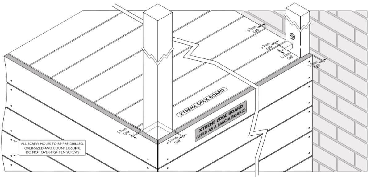
A 5mm to 7mm gap is required around posts or other protrusions in the decking. As mentioned in the substructure information any protrusions should have joists fitted around them so that the ends of boards are fully supported.
Diagram I
CleverDeck Original/Eco-Pro Composite Timber Decking – Domestic Fixing Specifications
| Maximum joist distance (centre to centre) laid at 90 ° to the joist | 450mm* |
| Maximum joist distance (centre to centre) laid at 60 ° to the joist | 400mm* |
| Maximum joist distance (centre to centre) laid at 45 ° to the joist | 350mm* |
| Maximum joist distance (centre to centre) laid at 30 ° to the joist | 250mm* |
| Maximum stringer spacing for stairs (centre to centre) (Note: Stair installation using CleverDeck should always include a riser board) | 300mm |
| Minimum ground Clearance over well drained ground | 100mm |
| Minimum ground Clearance over concrete (with no water pooling) | 25mm |
| Minimum spacing between boards (side to side) | 2-3mm |
| Minimum spacing at end of boards (abutting a wall) | 5mm |
| Minimum spacing from boards running parallel to a side wall | 5mm |
| Maximum overhang of boards past supporting joist (applies to edge boards or stair treads only) | 10mm |
| Maximum overhang of boards past supporting joist (applies to length only) | 50mm |
| Spacing required for butt joins in the deck ( for boards up to 3 metres long and board is below 30°C) | 2-5mm** |
| Spacing required where boards meet protrusions in the deck (for boards up to 3 metres long) | 5mm |
| Spacing required where boards meet protrusions in the deck (for boards over 3 metres long) | 7mm |
| Minimum spacing for screw fixings from the edge of the board | 25mm |
| Space between butt end and breaker board | 2–7mm** |
| Space between mitre joints (for boards up to 3 metres long and board is below 30°C) | 2-5mm** |
*Maximum recommended centre-to-centre spans using a minimum of three joists. Closer joist spacing improves the strength of the deck so a joist spacing of 400mm will provide more strength than a spacing of 450mm and if you reduce the spacing to 300mm it will be stronger again.
** Will depend on geographical region, installed temperature and likely temperature change over the year.
CleverDeck Original/Eco-Pro composite timber decking must not be applied directly to a solid surface.
Commercial installations will need to be assessed on a case by case basis.
Fixing details and specifications may change without notice.
For further information regarding your CleverDeck Original/Eco-Pro composite timber decking please Contact Futurewood
CleverDeck Xtreme®
Composite decking has unique characteristics and requires specific fixing requirements that differ from timber.
Storage
CleverDeck Xtreme composite decking must be stored flat and dry and off the ground. Standard 5.4 metre long packs of CleverDeck require a minimum of seven gluts (supports) under the pack for proper storage.
Take care when handling CleverDeck Xtreme composite decking as the boards are finished and ready to use and rough handling might cause visible scratches and marks on the deck boards.
Safety and Tools
As with any building project you should ensure that the correct tools and proper protective equipment are being used. It is the responsibility of the user to follow safe practices when using any tools during the installation process. Remember that CleverDeck Xtreme composite decking is heavier than most traditional timbers and should be lifted and carried with care.
CleverDeck Xtreme composite decking can be drilled, cut or fastened with normal woodworking tools.
In order to maintain clean cutting of the deck boards Futurewood recommends using a minimum 20 tooth carbide tipped saw blade. All other cutting tools should be carbide tipped and kept sharp.
Foundation and Sub-structure & Coverage (Refer diagram X-1)
CleverDeck Xtreme composite decking cannot be used as a component of the foundation or substructure.
When constructing the substructure care must be taken to ensure that the joists are level, straight and square as CleverDeck Xtreme composite decking will conform to the level and orientation of the joists.
An appropriate allowance for fall per metre of deck must be made when constructing the deck substructure. The deck should fall away from the structure. There must be enough fall on the boards so that any water that falls on the deck can run-off. If the fall is insufficient to allow run-off then water puddling will most likely occur.
Boards fixed across the deck at angles other than 90 degrees to the joists require closer joist spacing. Check the fixings specifications table on page 15 to make sure that you have the correct spacing between the joists. As a rule, the closer the joists the better the deck.
Futurewood recommends the use of a good quality self-adhesive joist protection tape to protect the timber joists under your deck boards. The joist tape will ensure that the top of the joists remain dry and stop any water/moisture from sitting between the bottom of the deck board and the joist improving the overall quality of your deck installation and reducing the risk of your joists rotting prematurely.
The 138mm wide CleverDeck Xtreme composite decking board combined with the Futurewood Combo Deck Clip provides a cover of 144mm or 7 boards per lineal metre.
The 185mm wide CleverDeck Xtreme composite decking board combined with the Futurewood Combo deck clip provides a cover of 191mm or 5.25 boards per lineal metre.
Additional joists will be required where breaker boards are used in the deck design. Read through the section below referring to breaker boards and determine your deck design before you calculate how many joists will be required for the deck.
The decking boards can overhang the subframe by up to 50mm in length. The decking boards can overhang the subframe by 10mm in width or a combination of the subframe and fascia board by 10mm in width if the fascia board is level with the joists. Consideration should be given to the overall deck size and the number of boards required to cover the deck.
You can start from the inner or outer edge of the deck depending on whether you are using full boards or whether you need to cut the board which is normally against a wall of an existing structure. The deck boards will be installed across the deck and the last board (finishing board) may need to be trimmed in order to fit in the space against the house or structure. Due to normal manufacturing tolerances and the potential for a slight difference in spacing between deck boards we do not recommend trying to pre-determine the width of the final board (the outer board must finish flush or no more than 10mm in width past the joist or fascia board). Any cut outs around protrusions such as a verandah posts or balustrades need to be fully supported.
Butt joins should only occur over a double joist. (Only recommended for boards up to 3 metres long).
CleverDeck Xtreme composite decking should not be attached directly to any solid surface or watertight flooring system, such as concrete, brick or tiled patios, waterproof membranes or roofing. If fixing over concrete the decking board can be fixed directly to a batten that is in contact with the concrete. A minimum 25mm batten is required. When fixing over concrete it is critical that no water is allowed to pool under the deck. Good drainage is essential and the joists should ideally run in the direction of the fall of the concrete. If the joists need to run across the fall then they should be raised or checked out accordingly so that water will not pool behind them.
Ventilation is a necessary requirement under and around your CleverDeck Xtreme decking boards. The Futurewood Combo Deck Clips provide a 6mm gap between each CleverDeck Xtreme composite decking board. 300mm clearance is an ideal distance between the boards and the surface beneath the deck, however the minimum ground clearance required is 100mm. Do not completely seal off deck ends to allow some airflow, any water must be able to drain away freely.
Failure to correctly install your CleverDeck composite decking may void your warranty.
The area under the deck should be dry and clear of vegetation. Drainage will be required if the ground below the deck typically holds water.
Diagram X-1
Adjustable Pedestal & Aluminium Joist SubFrame System
Futurewood has designed a subframe grid system consisting of an aluminium joist and adjustable pedestals. When installed with joists at 450mm centres and pedestals positioned under the joists at 450mm centres creating a 450mm grid system, the substructure has been designed and tested for a safe working load of 2KN/m2 (uniformly distributed load) or an applied load located anywhere on the span of the joist of 1.4 KN. You have the choice of standard, 18mm-30mm and 30mm-60mm adjustable pedestals (other heights available by request) that can be used in conjunction with the Futurewood 25mm Ultra low Aluminium Joist System. The pedestal and joist system can be used together on concrete or tiled patios/balconies where there is insufficient height to have traditional stump, bearer and joist subframes. The pedestal and aluminium joist subframe should be installed on a solid surface such as a concrete or tiled patio, alfresco or a stand alone paved area. If you wish to install over bare earth, the earth needs to be compacted, well drained and a geomembrane needs to be laid over the earth. Appropriate concrete pavers can then be positioned in a 450mm grid pattern for the pedestals to be placed on.
Colour and Orientation
The variation in colour tones and patterns on each of the CleverDeck Xtreme composite decking boards and between boards is part of the charm and appeal of this range of composite decking.
The grain or patterning of CleverDeck Xtreme composite decking will also reflect light differently depending on the orientation of the boards. To ensure a random look across the deck it is necessary to sort the boards before installation and make sure that darker and lighter boards are spread evenly across the deck as well as orienting all deck boards so that they run in the same grain direction.
Starting, Finishing, Edge & Fascia Boards (Refer diagram X-2 and X-3)
The first board laid on your deck is referred to as the starting board and will normally be installed with one “free” edge typically gapped against the side of a wall/structure or at the outside edge of the deck.
With the CleverDeck Xtreme composite decking you can use a regular deck board or an edge board as your starting board.
When using a regular deck board as the starting board it can only be fixed with the Futurewood Combo deck clip on the back edge of the board so you need to use the Futurewood Starting/Finishing (S/F) clip to secure the outer edge of the starting board. The S/F clip should be positioned close to the outer edge of the deck joists at 900mm intervals (every 2nd joist) so that the fascia board can be fitted flush against the ends of the joists/subframe. Fix the S/F clips to the joists then push the starting board in to the clip at a slight angle (about 30 degrees) so that the clip engages fully in the groove.
If the outer edge of the deck is going to be visible and you do not want to see the S/F clip or the groove on the edge of the first board then you can use a CleverDeck Xtreme composite timber Edge board as a fascia board. The Edge board has a squared off, finished edge. Fix the board with this edge up so that the finished height is level with the top of the deck board to hide the S/F clip and the groove in the outer deck board. The CleverDeck Xtreme composite timber Edge board has a groove in the back of the board towards the squared off edge and you can use the S/F clips to provide a concealed fix for this edge of the board, however the bottom edge of the board will need to be pre-drilled and face fixed unless you are running multiple boards as fascia boards in which case you can use the Combo deck clips in the grooves between boards to fix them.
If you are using an Edge board as the first deck board it is fixed with a combination of the Futurewood Combo deck clip on the back edge of the board and the S/F clip concealed in the groove that runs through the back of or underneath the board. The S/F clip should be fixed to the joist based on whether there will be a slight overhang of the edge board over the top edge of the deck or over any fascia board positioned under the Edge board (up to 10mm is allowed). One S/F clip every 450mm or every joist is required. Fix the S/F clips to the joists then lower the Edge board over the top of the clips and slide the board forward so that each clip fully engages in the groove of the board.
Before screwing down the Combo deck clips on the back edge of your starting board make sure that you place your next (second) deck board over the deck clips so that both edges of the deck clip are concealed (inside the groove on the back edge of the starting board and the front edge of the second board).
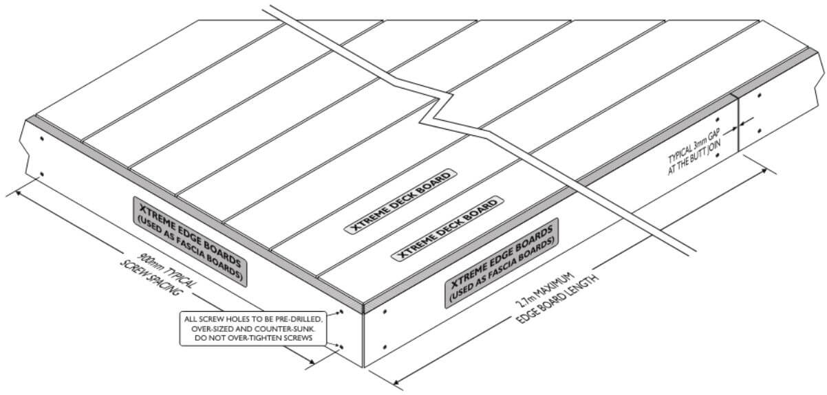
The finishing or last board should be treated in the same way as the starting board. The width of the finishing board can be reduced as required by sawing so that it can fit in between the adjacent structure and the 2nd last board. Grooves can be cut in to the board edge at 900mm intervals (every 2nd joist) using a router or biscuit cutter to allow starting or finishing clips to be used on the cut board edge. If the cut section of the finishing board is less than 100mm in width we recommend using noggins between each joist.
When using CleverDeck Xtreme composite timber Edge boards as fascia boards they should be fixed using a combination of S/F clip and screws or Combo deck clips at a maximum of 900mm centres to an appropriate frame fixed to the sub frame. When using screws fixed through the face of the Edge board pre-drill and pre-countersink all screws.
As the CleverDeck Xtreme composite timber board is a co-extrusion it is advisable to cover any cut edges including the cut ends of the boards so that the different coloured core of the board is not seen. The CleverDeck Xtreme composite timber Edge board is made for this purpose and can be fixed as the first decking board from the outer edge of the deck (if visible). The Edge board can also be used as a picture framing style board at the side of the deck to cover the visible edge of the cut board ends.
Diagram X-2
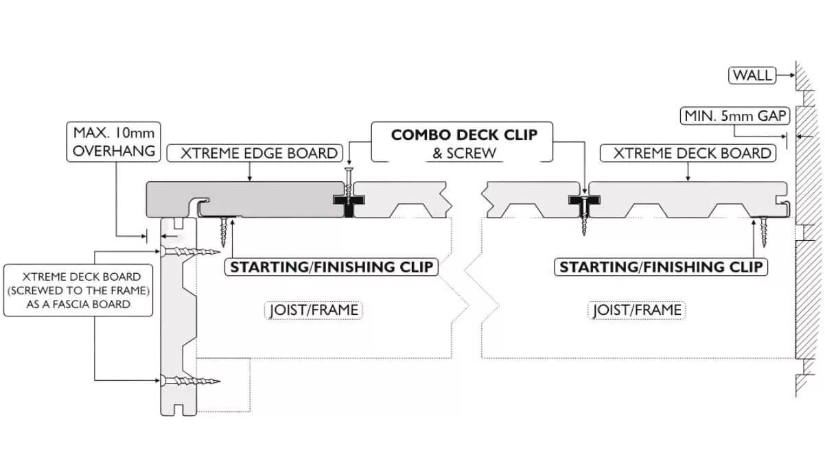
Diagram X-3
Breaker Boards And “Border Picture Frame” Boards (Refer diagrams X-4, X-5, X-6, X-7, X-8)
A breaker board is a regular deck board that is positioned in your deck design at 90 degrees to the main deck boards to provide the necessary gap for expansion and contraction between the ends of deck boards. (refer to the table on page 15 for correct gapping).
Wherever a breaker board is positioned it must be supported by a minimum of 2 – 45mm wide joists and the ends of the boards butting up to either side of the breaker board need to finish on a full joist meaning that 4 standard 45mm wide joists are required to adequately support a breaker board. If multiple breaker boards are being used a ladder joist or noggins between joists can be used to fully support all the breaker boards at a maximum of 450mm centres.
A picture frame board or border will need 2 joists to support it and 1 joist to support the deck boards that run up to the picture frame board. Due to the expansion and contraction of the boards, a picture frame or border should not exceed 3 metres in length if it is to be butt joined.
Because CleverDeck Xtreme composite decking comes in standard 5.4 metre long lengths the preferred method of installation is to use a breaker board rather than having randomly spaced butt joins spread across the deck. Depending on your overall deck size/shape you may need to allow for the inclusion of one or more breaker boards in the design of your deck. The incorporation of the breaker board can greatly enhance the character and appearance of your deck as well as allowing you to use potential off cuts (helping to minimise overall board wastage). Additional joists will be required in your sub floor construction to fully support the breaker boards wherever they are being used.
Running long boards with a butt join may result in a gap of more than 10mm once the boards have cooled and contracted. If staggered butt joins are to be used, we recommend that you contact Futurewood to discuss your specific fixing options.
Breaker boards should be fixed using the Combo deck clip. Combo clips are positioned at the end of the deck boards where they meet the edge of the breaker board.
The breaker boards should be left loose and placed in between the regular deck boards then the breaker board can be evenly spaced between either side of the regular deck boards and the Combo deck clips can be pushed against the breaker board so that the nose of the clip engages in the groove of the breaker board before driving home the screws.
We recommend that any breaker boards, whether they are butted together or are a single board, do not exceed 3 metres in length (e.g. a 5.4 metre board would be cut in half producing 2 x 2.7 metre boards). The butt joins between these boards should be gapped according to the table on page 15. This will help to minimise the potential for an excessive gap developing at the butt join between the breaker boards or for a single longer breaker board to expand beyond the side of the deck.
Because the CleverDeck Xtreme composite decking board is a co-extrusion it is advisable to cover any cut edges including the cut ends of the breaker boards or picture frame boards. The easiest way to cover the cut ends of any boards is to use the CleverDeck Xtreme composite timber Edge board as a vertical fascia board bringing this board up level with the deck surface and hiding any board edges or ends (see previous section relating to edge boards and fascias).
If a fascia board is not being used or if the CleverDeck Xtreme composite timber Edge board is being used as the first board or last board at the deck edge, then it will be necessary to vary the regular layout for the breaker board or picture frame board to make sure that the ends of these boards are not seen. In this case the preferred layout when using a breaker board is to finish the breaker board before the deck edge, one board back and use a CleverDeck Xtreme composite timber Edge board to run continuously across the end of the breaker board. In this scenario the longer edge board will need to be cut back to 2.7 or 3 metre maximum lengths and appropriately gapped at the butt joins.
Any exposed deck corners will need to be finished with the 2 board ends meeting at a mitre and with the mitre join appropriately gapped according to the table on page 15.
Diagram X-4
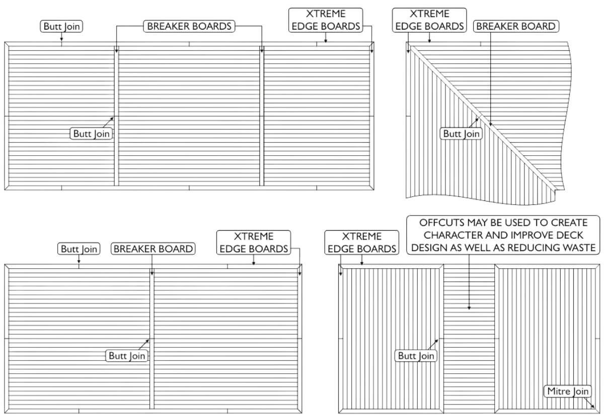
Diagram X-5
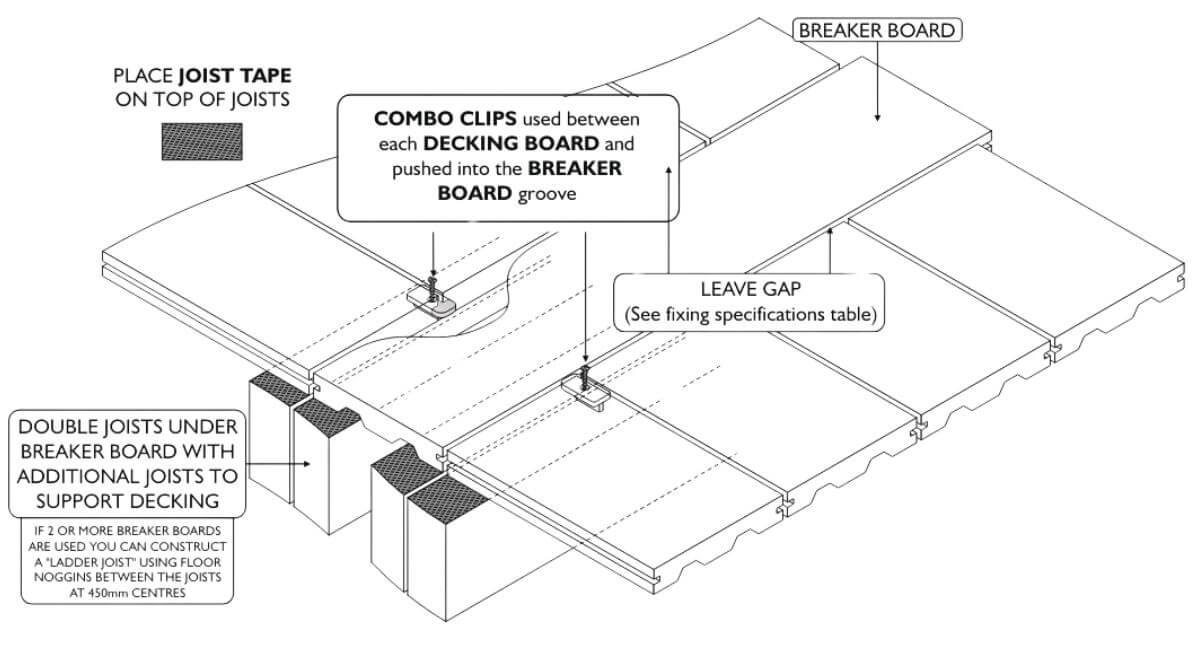
Diagram X-6
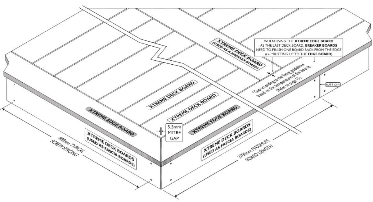
Diagram X-7
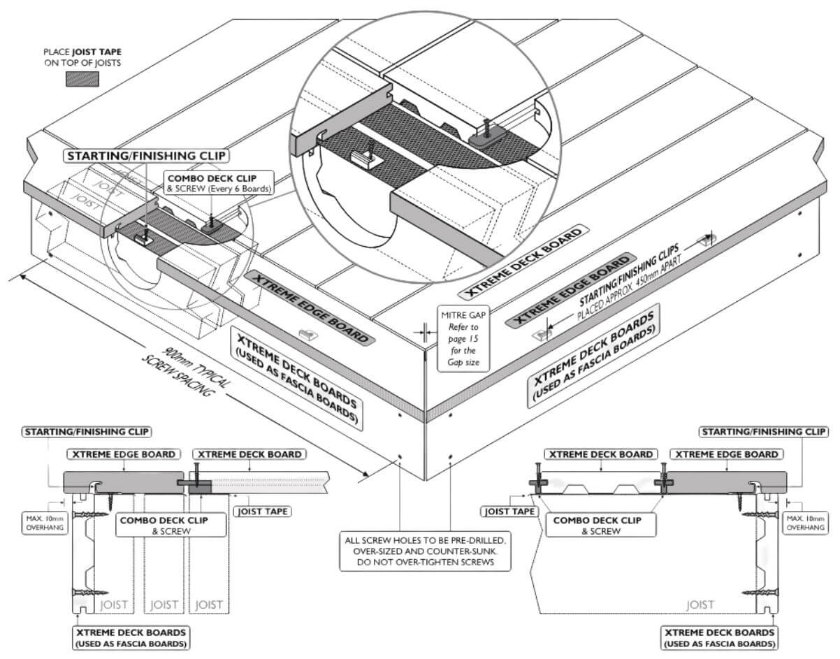
Diagram X-8
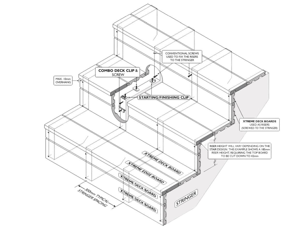
Stairs (Refer diagram X-9, X-10)
CleverDeck Xtreme composite decking boards can be used as stair treads and for stair risers.
When using CleverDeck Xtreme composite decking boards for stair treads they must be supported at a maximum of 300mm centres by a stair stringer or other structural support. A typical stair tread or riser will normally require more than one CleverDeck Xtreme 138mm wide composite decking boards to make up the minimum required stair tread width or riser height. The final total stair tread width or riser height might require one or more of the CleverDeck Xtreme composite decking boards to be cut to reduce the overall width or height of that board. The solid CleverDeck Xtreme composite decking boards can be easily cut along their width.
There are several different ways that stairs can be built, with or without risers and with stair treads overhanging or flush. CleverDeck Xtreme composite decking boards can be used in all examples, but the fixing methods vary and using concealed fixing is not possible for all installation methods.
In some cases, CleverDeck Xtreme composite decking boards will need to be fixed as stair treads or risers by screwing through the face of the board. Note: all holes must be pre-drilled and pre-countersunk to ensure a neat finish and not risk damaging the boards.
When 2 full width boards are being used for the stair tread Combo deck clips can be used between the boards and starting/finishing clips can be used at the back edge of the stair tread if they are hidden at the back/underside of the stairs or if the riser comes down against the back of the stair tread or on top of it. The front edge of the front board can be fixed with starting/finishing clips if the stair riser is finishing flush with the stair tread on the outside of the deck board.
If the front stair tread has an exposed edge and is mounted over the top of but flush with the riser you will need to use a CleverDeck Xtreme composite timber Edge board that has one square edge. For this type of installation, the front edge of the front stair tread will need to be fixed to the stringers using a starting/finishing clip.
If the front stair tread has an exposed edge and is overhanging the riser (the maximum overhang is 10mm) you will need to use a CleverDeck Xtreme composite timber Edge board that has one square edge. For this type of installation, the front edge of the front stair tread will need to be fixed to the stringers using a starting/finishing clip.
If stair risers are included in the stair design, it might be possible to use a concealed fix starting/finishing clip on one edge, but it is most likely that face fixing the riser by screwing through a pre-drilled and pre-countersunk hole will be necessary to fully fix the riser.
Diagram X-9
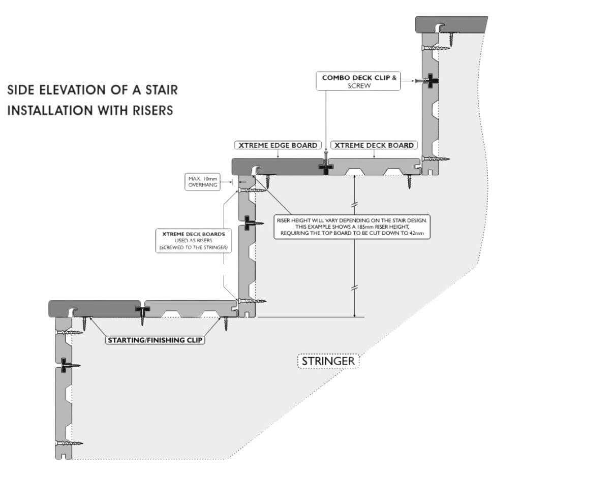
Diagram X-10
Fastening
Futurewood Deck Clip System (Refer diagram X-11)
The Futurewood Deck Clip System has been specifically designed for fixing CleverDeck Xtreme boards and provides the added value and appearance of a concealed fix while saving time and money on the installation of the deck. It is highly recommended to use Futurewood Deck Clips & screws when installing CleverDeck Xtreme composite decking.
Futurewood Combo Deck Clips and Locking Clips are supplied with blackened stainless-steel screws for fixing to either timber or metal joists. These screws have specially made, smaller screw heads to fit between the decking boards and are made with a T15 drive. T15 drives are supplied with these clips/screws. Starting/Finishing clips come with stainless-steel screws for timber joists or stainless-steel pop rivets for fixing to metal joists and BAL clips are supplied without screws.
Make sure that you specify the correct clips based on the table below;
Note: Screws for self drilling into metal are designed to cut through soft/mild hardness metal to a maximum thickness of 1.6 mm. Harder/thicker metals will need to be pre-drilled.
| Part Number | Quantity per pack/box | Type | Screws for Joist Type | Coverage based on 450mm joist |
|---|---|---|---|---|
|
M-100
|
100 | Combo deck clips c/w 410 S/S screw + 2 -T15 drivers | Metal | 6 square metres |
|
T-100
|
100 | Combo deck clips c/w 316 S/S screw + 2 -T15 drivers | Timber | 6 square metres |
|
SFM-20
|
20 | 304 S/S starting/finishing clips c/w 304 S/S pop rivet | Metal | 3 x 5.4 metre deck boards |
|
SFT-20
|
20 | 304 S/S starting/finishing clips c/w 304 S/S screw | Timber | 3 x 5.4 metre deck boards |
|
LM-20
|
20 | 316 S/S locking clips c/w 410 S/S screw + 1 -T15 driver | Metal | 20 boards regardless of length |
|
LT-20
|
20 | 316 S/S locking clips c/w 316 S/S screw + 1 -T15 driver | Timber | 20 boards regardless of length |
|
BAL-100
|
100 | 304 S/S BAL 2mm gap deck clips – no screw | Metal/Timber | 5.5 square metres |
Futurewood Combo Deck Clips should be used at each joist regardless of joist spacing.
Locking Clips are used to stop the individual deck boards from creeping in one direction or the other even though they are fixed with the Regular deck clips. The locking clip will help to prevent the board from creeping or “walking” along the deck. This creeping or “walking” can occur due to the continual expansion and contraction of CleverDeck Original boards with changing temperatures.
One locking clip should be used in place of the Combo deck clip on either side of every board, at the joist that is closest to the centre of each board, regardless of board length.
Note: The locking clip will not work if it is not positioned close to the centre of the board.
Combo deck clips should be loosely positioned in the groove of the deck board over each joist as well as one locking clip over the joist that is closest to the centre of the board before sliding the next board in to position. Once the starter board is aligned and fixed in position you can prepare up to 7 boards pushed together with deck clips in position over each joist. Apply enough force against the last board you are fixing in the “set” so that the boards are pushed close together (you can use a string line to ensure that the boards are straight and true) and then fix the set in place by screwing down the deck clips on the inside of the outer board (the last row of deck clips that have a board on either side of them). make sure that all deck clips are evenly spaced over the joists before fixing them. Once the outer board is secure, you can screw down all the deck clips between the other boards (you may want to leave these clips unfastened until all the boards have been positioned on the deck just in case any last-minute adjustments to any boards are required). Repeat this process until you reach the finishing board.
Breaker boards clips are used to secure any breaker boards that are part of the deck design (refer to the breaker board section on page 6).
Starting/finishing board clips are used on the first and last board on the deck (refer to the Starting boards section on page 4).
These clips are also used to fix one side of the CleverDeck Xtreme composite timber Edge boards.
The BAL is a special clip designed to give a 2-3mm gap between boards as required in a high bush fire zone. Contact Futurewood for more information.
Diagram X-11
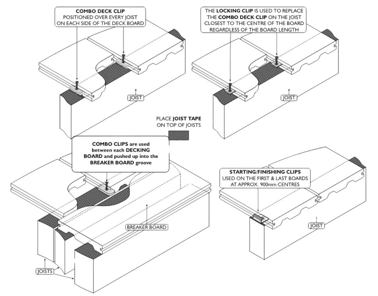
Diagram X-12
When fixing a butt joint use a Combo Deck Clip on both sides of each deck board (4 in total for each butt join, refer diagram X-12).
Drivers should be adjusted to a low or medium torque setting when fixing all Futurewood Deck Clips to ensure that the screws are not “over driven” in to the clips.
Additional care must be taken when fixing Combo deck clips to steel joists to ensure the screws cut properly and to reduce the risk of the driver or screw head stripping. If the screw does not self drill, the metal may be too hard or too thick and will need to be pre-drilled.
We recommend that a slow speed and minimal force is used to drive the screw through the clip until it is touching the steel. At this point the speed of the driver should be increased to approximately 1000rpm to allow the cutting edge on the screw to cut through the steel. Too much pressure or too little speed may cause the screw to go off line and will strip out the screw head and or the driver. Once the screw has cut through the steel, any pressure on the driver should be reduced immediately to stop the screw from driving through the clip.
Combo deck clips provide an automatic spacing of 5.5mm (+/- manufacturing tolerances) between each board.
The Futurewood Deck Clip System provides the best fixing option for CleverDeck Xtreme composite decking as the clips are designed to allow the decking to “work” with the deck clip maintaining independent expansion and contraction between the decking boards and the joists. This independent fixing method virtually eliminates the pressure build up on the fastenings that can occur when the decking is fastened directly to joists.
Screw Fixing
Screw fixing is generally not needed or recommended other than for some stair installations where short boards are used, however, if there is a need to screw fix some boards on your deck please note the following instructions.
Pre-drilling and pre-countersinking are essential in order to reduce the risk of splitting when screwing directly in to the face of the CleverDeck Xtreme composite decking. A minimum screw length of 60mm is required. When fixing a butt joint two screws are required to be positioned 25mm from the outside edge of each board and a minimum of 25mm from the end of each board. Drivers should be adjusted to a low or medium torque setting when fixing screws in to CleverDeck Xtreme composite decking. Screws should not be “over driven or over tightened” in to the decking.
Screw fixing directly through the CleverDeck Xtreme composite decking board is not recommended on steel joists when the board length is over 3 metres due to the different expansion and contraction characteristics of the two materials.
Nail Fixing
Nailing is not recommended.
Spacing (Refer diagram X-13 below)
CleverDeck Xtreme composite decking expands and contracts lengthways due to changes in temperature (there is minimal change to the width of the board). It is critical that you have all the boards at roughly the same temperature and below 30°C as boards cut at different temperatures will affect the appearance of the finished deck.
The longer the board the greater the potential for a change in length due to temperature change. All boards must be the same temperature during the installation process (measuring & cutting). All boards should be kept in the shade so that they are not affected by direct radiant heat and are at a similar temperature. If there is no shade on the site, make sure that all measuring and cutting is done in the morning when the boards are still cool from the previous night. Once the boards are exposed to direct sunlight, they will absorb radiant heat and increase in length.
A 5.4 metre long board will grow in length by approximately 2.5mm for every 10°C increase in temperature. The board will contract in length by the same amount when the temperature of the board cools.
Even on a day of mild temperatures and minimum temperature change the boards may vary in temperature by 30°C or more if moved between direct sunlight and shade.
Boards should always be measured/cut/installed at cooler ambient temperatures (below 30°C). Therefore, in summer months and tropical areas installation should occur in the morning.
Butt joins are not recommended but if they must be used the boards should be less than 3 metres in length (as is the case of the breaker boards or picture frame boards). A 2-5mm gap should be left to allow for expansion when installing the boards at recommended temperatures, refer to the gapping table on page 15 for more information. butt joins should always occur over a double joist or cleat (minimum 90mm x 45mm) to allow for the use of a deck clip and screw at the ends of each board (4 standard deck clips are required -2 deck clips per side per butt join refer diagram X-12 page 13).
It is highly recommended that boards over 3 metres in length are not butted end to end (this applies for either a continuous run of boards or an angled or mitred join). Running long boards with a butt join may result in a gap of more than 10mm once the boards have cooled and contracted. The preferred method of deck design is to use a breaker board (refer to the breaker board fixing information on page 6). Other fixing options might be applicable if numerous butt joins are required. Please contact Futurewood for information regarding alternative butt joining options.
A 5mm to 7mm gap is required around posts or other protrusions in the decking. As mentioned in the substructure information any protrusions should have joists fitted around them so that the ends of boards are fully supported.
Diagram X-13
CleverDeck Xtreme Composite Decking Domestic Fixing Specifications
| Maximum joist distance (centre to centre) laid at 90 ° to the joist | 450mm* |
| Maximum joist distance (centre to centre) laid at 60 ° to the joist | 400mm* |
| Maximum joist distance (centre to centre) laid at 45 ° to the joist | 350mm* |
| Maximum joist distance (centre to centre) laid at 30 ° to the joist | 250mm* |
| Maximum stringer spacing for stairs (centre to centre) (Note: Stair installation using CleverDeck should always include a riser board) | 300mm |
| Minimum ground Clearance over well drained ground | 100mm |
| Minimum ground Clearance over concrete (with no water pooling) | 25mm |
| Minimum spacing between boards (side to side) | 2-3mm |
| Minimum spacing at end of boards (abutting a wall) | 5mm |
| Minimum spacing from boards running parallel to a side wall | 5mm |
| Maximum overhang of boards past supporting joist (applies to edge boards or stair treads only) | 10mm |
| Maximum overhang of boards past supporting joist (applies to length only) | 50mm |
| Spacing required for butt joins in the deck( for boards up to 3 metres long and board is below 30°C) | 2-5mm** |
| Spacing required where boards meet protrusions in the deck (for boards up to 3 metres long) | 5mm |
| Spacing required where boards meet protrusions in the deck (for boards over 3 metres long) | 7mm |
| Minimum spacing for screw fixings from the edge of the board | 25mm |
| Space between butt end and breaker board | 2–7mm** |
| Space between mitre joints (for boards up to 3 metres long and board is below 30°C) | 2-5mm** |
*Recommended centre-to-centre spans using a minimum of three joists. Closer joist spacing improves the strength of the deck so a joist spacing of 400mm will provide more strength than a spacing of 450mm and if you reduce the spacing to 300mm it will be stronger again.
** Will depend on geographical region, installed temperature and likely temperature change over the year.
CleverDeck Xtreme composite decking must not be applied directly to a solid surface.
Commercial installations will need to be assessed on a case by case basis.
Fixing details and specifications may change without notice.
For further information regarding your CleverDeck Xtreme composite decking please Contact Futurewood
EnviroSlat® Decorative Cladding and Screening
EnviroSlat Decorative Cladding and Screening can help you achieve a stunning design/finish to your project that will require minimum maintenance compared to traditional timber and is made from recycled, environmentally friendly material which won’t rot.
Storage
It is important to ensure that EnviroSlat is not exposed to direct sunlight or excessive temperatures while stored in packs in order to reduce excessive heat build-up.
EnviroSlat must be stored flat and dry and off the ground; Standard 5.4 metre long packs of EnviroSlat require a minimum of seven gluts (supports) under the pack or be placed on an appropriate length custom length pallet for proper storage.
Working with EnviroSlat
EnviroSlat will expand or contract in length with rising or falling temperatures. All boards should be conditioned before cutting so that they are at an even temperature. Boards are best cut in the shade before they are exposed to radiant heat and in ambient temperatures under 30 degrees Celsius (in the morning). When cutting lengths of EnviroSlat you should take in to account the temperature of the conditioned boards and allow for expansion or contraction of the boards based on the likely temperature fluctuations over the year at the site.
You should allow for some expansion between boards that are butted together or where boards are butted against a post or other structure. We recommend a minimum 5mm gap between the end of an EnviroSlat board and any frame, xed surface or another board. EnviroSlat will expand by approximately 7-9mm (3-4.5mm at each end) over a board length of 5400mm based on a temperature increase of 40 degrees Celsius.
The surface of EnviroSlat could be as much as 25 degrees Celsius warmer than the ambient temperature when subjected to continuous direct sunlight. Therefore the board could reach a surface temperature of up to 65 degrees Celsius on a day when the ambient temperature reaches 40 degrees Celsius.
Fencing/Screening – Construction and Fixing
EnviroSlat is designed to be fixed directly to posts that are fixed in/on the ground. The posts can be made of timber, steel or aluminium and need to be of a suitable cross section and strength to hold the intended fence size/weight.
The maximum span for continuously fixing EnviroSlat boards is 900mm between support posts in order to minimize flexing caused by thermal expansion/ contraction of the boards. For single spans the maximum distance between support posts is 600mm.
Spacing between slats comes down to personal preference and the amount of privacy, shade and air flow that is required, although most projects are installed with 10-20mm gaps between boards. Boards can be butted side to side if required as there is minimal expansion across the board width.
EnviroSlat 70mm x 15mm boards can only be fixed with screws inserted through the front face of the board (front fix) where the screw head will be visible. Button head, wafer head or countersunk screws in either 8 or 10 gauge should be used to front fix EnviroSlat boards. When front fixing it is recommended that you pre drill all the holes for the screws. If using countersunk screws both the hole and the countersink need to be pre-drilled. All holes should be 1-2mm larger than the shank of the screw but not too large so that they are still hidden under the head of the screw. Do not over tighten the screw and ensure that it does not bury in to the surface of the EnviroSlat board. Screws should be positioned a minimum of 25mm from any profile edge for the 70mm x 15mm profile to avoid any risk of the boards splitting.
The expansion and contraction of EnviroSlat boards that are fixed with screws through the board is reduced based on the closer spacing of screws along the length of the board and the 1-2mm oversize holes for the shank relieves some of the pressure from the expanding or contracting board on the screws themselves.
- All screws should be plated or made from stainless steel or brass
- If coloured screws are required we recommend pre-painting your screws before installation
- EnviroSlat profiles should be fixed with one screw at each support point
- Nailing is not recommended for securing EnviroSlat
Decorative Cladding – Fixing
EnviroSlat decorative cladding is designed to be fixed directly to battens in either the horizontal or vertical direction. The battens can be made of timber, steel or aluminium and need to be of a suitable cross section and strength to hold the intended weight.
EnviroSlat profiles can also be fixed directly to a suitable wall substrate.
Futurewood recommends that EnviroSlat decorative cladding should be fixed at either 450mm or 600mm centres.
Spacing between slats comes down to personal preference based on the “look” that you wish to achieve or the amount of privacy, shade and air ow that is required.
EnviroSlat 40mm x 30mm and 60mm x 40mm slats as well as larger custom made profiles of decorative cladding boards can be either face fixed or rear fixed.
Futurewood recommends using a 10 gauge countersunk screw when fixing through the front face of the board.
The thread type will be relevant to the material that the board is being fixed to. For rear fixing we recommend a 10 gauge coarse threaded particle board screw or similar. For face fixing it is recommended that you pre drill and pre countersink all the holes for the screws. All holes should be 1-2mm larger than the shank of the screw but not too large so that they are still hidden under the head of the screw. Do not over tighten the screw and ensure that it does not bury in to the surface of the EnviroSlat board. Screws should be positioned a minimum of 25mm from any board edge (15mm to 20mm for 40mm x 30mm profile) to avoid any risk of the boards splitting.
These thicker boards can also be fixed using a recessed screw and a push in plug to achieve a “concealed fix” – refer to Futurewood for more information.
The expansion and contraction of EnviroSlat boards that are fixed with screws through the board is reduced based on the closer spacing of screws along the length of the board and the 1-2mm oversize holes for the shank relieves some of the pressure from the expanding or contracting board on the screws themselves.
- All screws should be plated or made from stainless steel or brass
- If coloured screws are required we recommend pre-painting your screws before installation
- EnviroSlat profiles should be fixed with one screw at each support point. Fixing details and specifications may change without notice. For further information email [email protected]
- Nailing is not recommended for securing EnviroSlat
Colour & Surface Finishing
The colour of your EnviroSlat board will weather in the first 4-12 weeks of exposure to the elements.
After the initial weathering process the colour will be maintained over many years with only very slight changes year on year. The manufacturing process does allow for a very slight variation in colour from board to board and batch to batch of material. Slight colour change may also occur over time as part of the natural weathering effect.
Rough edges on cut ends can be removed using a fine abrasive paper.
Cleaning
EnviroSlat should be washed down periodically with a strong solution of household detergent (“Handy Andy” works well) in order to clean off accumulated dirt/grime.
EnviroSlat® Weatherproof Cladding
The following points need to be observed during the installation process of Futurewood’s Weatherproof Cladding.
General information
- Screw holes should be oversized and countersunk. The hole diameter should be 2mm larger than the screw shank diameter. A 9 – 10g (4.5mm – 5mm) screw size is recommended.
- Fixings screws should be driven home and not over tightened.
- All screws should be a minimum of 25mm from the end or edge of each board.
- The recommended sealant to be used with any butt joins or penetrations is H.B. Fuller Fulaflex 625 construction sealant (black).
- When butt joining, the inside surface of the board should be abraded with abrasive paper to ensure adhesion of the sealant.
- It is recommended that a string line is used to check that installed boards are parallel.
- A suitable Breathable Vapour Barrier needs to be installed between the studs and the Weatherproof Cladding.
Diagram A
Step 1. Preparation of the frame
- A suitable waterproof flashing should be installed at all internal and external corners, windows, doors or other penetrations.
- Before installing the cladding the wall studs need to be made plumb, ensuring that they are even and level and will provide a flat surface to fix the cladding to.
- If installing the cladding vertically battens will need to be installed over or between the studs at a maximum spacing of 600mm (however 450mm is the recommended spacing).
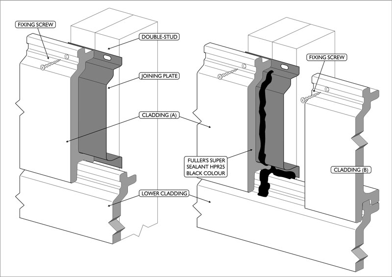
- A double stud or cleat needs to be positioned wherever the weatherproof cladding boards are being joined.
Step 2. Installation of Weatherproof Cladding boards “First or Starter Board” for horizontal installation
For horizontal installations
- Loosely fit a starter clip into the back of the cladding board and measure the distance between the centre of the hole in the starter clip and the bottom of the cladding board (it should be around 5mm).
- Use a string line or other suitable method so that a level mark can be made on each joist, then mark the screw position of the clip on each stud remembering that the bottom of the first board will sit below this mark.
- Screw the stainless steel starter clips in to place on each stud.
- Rest the first board in place on the starter clips and screw home the top of the first cladding board ensuring not to over-tighten the screws.
For vertical installations
- Loosely fit a starter clip into the back of the cladding board and measure the distance between the centre of the hole in the starter clip and the bottom of the cladding board (it should be around 5mm).
- Use a string line or other suitable method so that a mark can be made in a straight line on each batten, then mark the screw position of the clip on each batten remembering that the starting edge of the first board will sit to the side of this mark.
- Screw the stainless steel starter clips in to place on each batten.
- Push the first board in place on the starter clips and screw home the inside edge of the first cladding board ensuring not to over-tighten the screws.
Step 3. Butt joining Weatherproof Cladding Boards
- The proprietary butt joining plate should be used behind every butt join of the weatherproof cladding. The joining plate is designed to fix over a double stud or a stud and block.
- Composite boards will expand and contract with changes of temperature so care needs to be taken when cutting boards to length. The ambient temperature needs to be taken into consideration and if the surface of the board is warm to hot (ambient temperature above 25 degrees Celsius) then a gap of no more than 1mm should be left between boards at a butt join. If the surface of the board is cooler then a minimum 2mm gap should be left between boards at the butt join. * *NOTE: It is Important that the boards are stored in the shade prior to installation to ensure the temperature of each board is similar so that their relative lengths remain constant.
- The weatherproof cladding needs to have the shiny back of the board “abraded” with a coarse sand paper for approximately 50mm at the end of each board being joined over the backing plate.
- The black Stainless Steel backing plate needs to have a small bead of FulaFlex 625 black flexible sealant run from top to the bottom of the backing plate, approximately 20mm from the centre of the plate on one side. The backing plate then pushed into position behind one of the boards to be joined together leaving half of the backing plate exposed. This board (with the backing plate) is then screwed into position over the stud or block.
- Place the other side of the cladding board into position with the end 55mm from the first board. Place a small bead of the Fullers Sealant from the top to the bottom of the backing plate where the two boards will join, especially into the lower section, filling all gaps. Slide the board into place leaving either a 1 or 2mm gap based on the ambient temperature (see point 2 above) and then fix in this position with a screw. Any excess sealant should be left to dry and then trimmed off with a sharp knife.
Step 4. Fixing External and internal corners
- Internal and external corners can be finished using a powder coated aluminium section (Futurewood recommend a 76.2mm x 3mm equal angle available from Ullrich aluminium). The angle is attached with face fix screws and can be colour matched to suit downpipes, windows or other flashings that are in the vicinity of the cladding.
Aluminium Deck Frame System
These guidelines are for guidance only and do not overrule existing, relevant building codes.
Order Receipt and Storage
It is the responsibility of the person signing for the delivery of the CleverDeck Subframe to check off the items received against the delivery docket to ensure that all items are received.
Take care when handling CleverDeck Aluminium joists/bearers as the ends of the cut aluminium are quite sharp and can easily cut or mark any surfaces they contact. As the subframe system consists of long bearers/joists and smaller brackets, clips and screws be sure to store the components in such a way that the smaller items do not get lost on the building site.
Safety and Tools
As with any building project you should ensure that the correct tools and proper protective equipment are being used. It is the responsibility of the user to follow safe practices when using any tools during the installation process. Remember that the CleverDeck Aluminium joists/bearers have sharp edges, appropriate protective equipment should be worn to protect eyes from swarf or hands from cuts and abrasions.
CleverDeck Aluminium joists/bearers should be cut with a special purpose aluminium cutting blade used in a drop saw or an angle grinder. All cutting tools used should be kept sharp
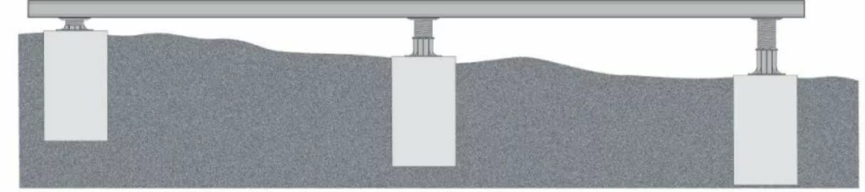
Planned Deck Height and Ground Contours
Once the finished deck height is established it is critical to determine the slope of the ground under the deck area to ensure that the right combination of joist, bearer and pedestal sizes are provided.
The deck plan will be designed based on the different heights required due to the lay of the land across the total deck area. Measurements should be taken across and the length and width of the deck in various locations where there is uneven ground.
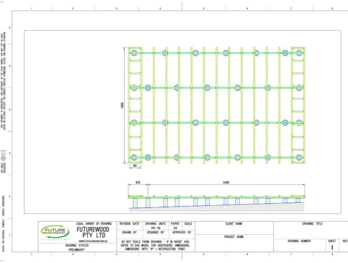
Deck Plan
The Futurewood CleverDeck Subframe is a complete system made up of various components to suit a given deck plan. The deck plan should be designed based on the layout of the decking boards that are being fixed to the subframe so that the subframe fully supports all aspects of the deck board design.
A typical deck plan will consist of pedestals that are spaced at intervals to suit the joist or bearer that they are supporting (refer to span tables).
The deck plan will include all the joists, bearers, and pedestals along with any brackets, clips and screws required and will show the pedestal grid spacing and the positioning of each of the brackets/clips.
Deck plans can be certified by a licensed structural engineer for an additional cost.
This is an example of a simple 5.4m x 4.8m deck subframe.
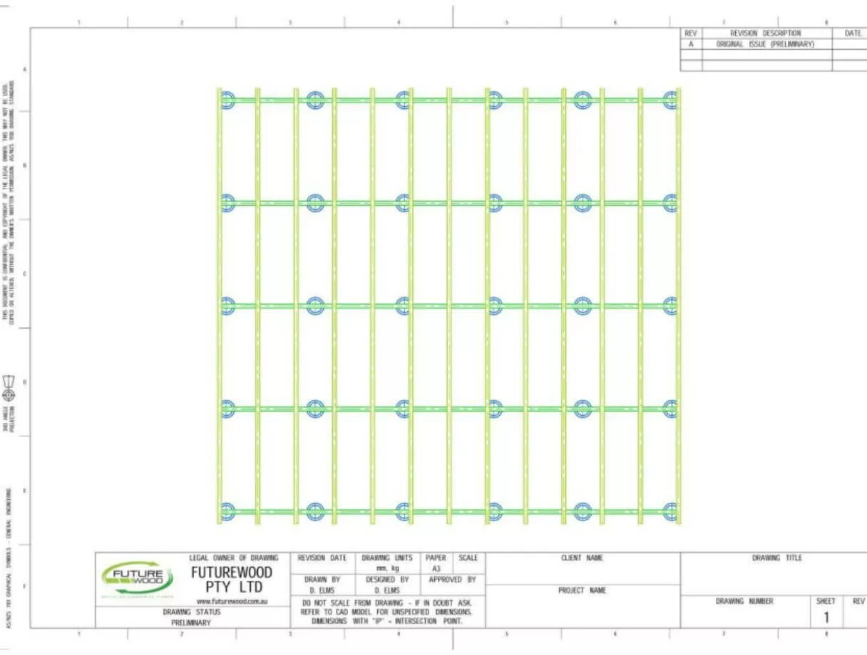
Please note that the sample deck plan below was drawn up for a specific deck design that includes 2 breaker boards on each side of the deck, and the ground the deck is built on has a 5 degree slope. Individual deck plans can be created for each individual deck.
Pedestals
Standard pedestal sizes are 14-19mm, 19-30mm, 28-42mm, 40-65mm, 60-105mm, 90-185mm, 185-320mm.
Once you establish your finished subframe height and levels you need to position the adjustable height pedestals in a grid pattern according to the subframe design/plan. Pedestals need to be positioned over an existing concrete slab or on footings that are constructed according to the local council regulations and soil conditions.
If the pedestals are being placed on an existing concrete slab that has a slope of up to 3 degrees, a slope corrector should be inserted under the pedestal base and adjusted between 0-3 degrees to level up the top of the pedestal. If the slope is greater than 3 degrees, the area under the pedestals will need to be levelled using a non-shrink structural grout.
The pedestals should be adjusted to achieve the rough height expected. The top plate should be inserted in the top of the pedestal and oriented for single or double bearer/joist use depending on your
subframe plan. When using a single bearer/joist the longest side of the top plate is running in the same direction as the bearer or joist so the bearer/joist is sitting over the centre of the pedestal. For double
bearer/joist use the top plate will be oriented so that the short side of the top plate is running in the direction of the bearer/joist.
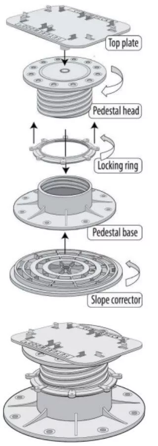
Once all the pedestals are roughly in position, the bearers/joists should be lined up in the appropriate direction and pushed between the lugs on the top plate until they snap over the bottom edge of the bearer/joist. The pedestals can then be adjusted to the required height. No screws are required.
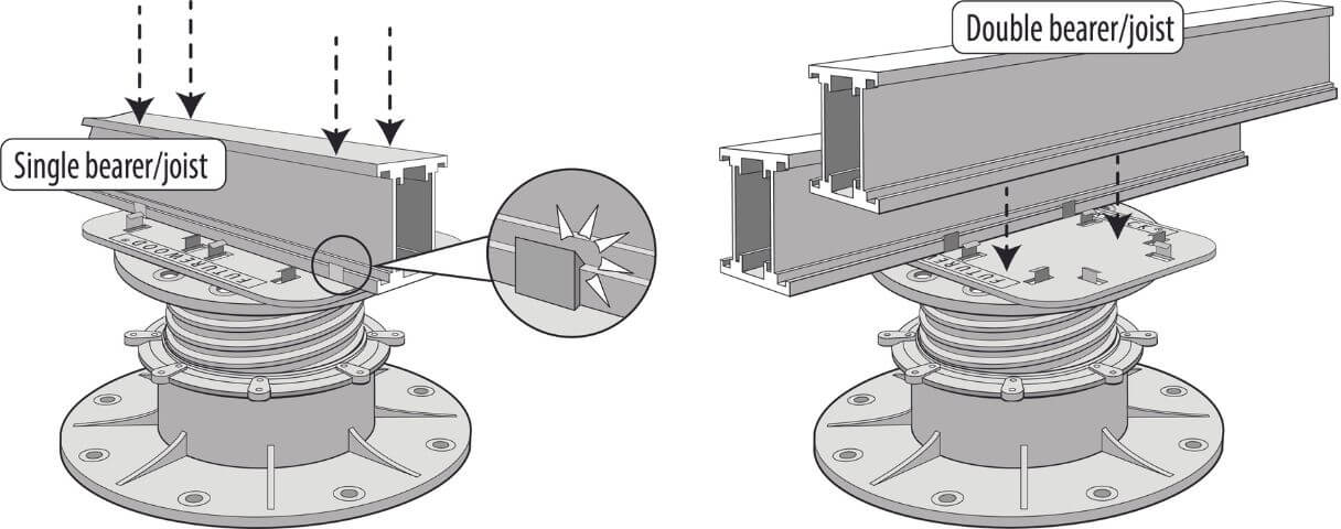
Once the joists or bearers are all in position and the correct spacing, height and levels are achieved the pedestal locking rings (if provided) should be tightened and the pedestal bases screwed to the substrate. Pedestals can also be glued in place or left unfixed so that the subframe becomes a “floating” subframe. If fixing over a waterproof membrane that cannot be punctured the subframe can be glued if an appropriate glue is used that will not damage the membrane and adheres to both the membrane and the pedestal base. The pedestals can also be left floating on the membrane.
Any gaps that are showing between the pedestal base and the substrate or the top of the pedestal and the top plate can be filled using an appropriate filler/glue.
As the pedestal bases are 200-220mm in diameter, pedestals that are positioned within 110mm of the edge of the deck will have the base of the pedestal extending past the outer edge of the deck.
Where this is not practical as the edge of the deck is against a wall or the outer edge is being covered with base boards/fascia, a dropper should be used (refer to dropper section of the fixing guide).
Joists / Bearers
Standard joist/bearer sizes are 25mm x 45mm, 50mm x 45mm and 90mm x 45mm and all standard bearers/joists are 5400mm long. Any of the 3 profile sizes can be used as bearers/joists depending on the deck design, deck height, and the required span.
25mm joists can be fixed directly to the concrete to achieve a minimum deck height of 48mm. The bearers/joists snap in place over the specially designed pedestal top plate.
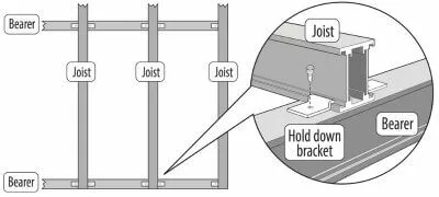
Joists are fixed to the bearers using 2 “hold-down” brackets, one on either side of the joist, for continuous joists and 1 bracket if the joist finishes at the outside edge of a bearer.
When joists need to be joined they need to be supported by a bearer or a pedestal under the join and then fixed with an aluminium joiner inside the joist using 2 screws per joiner. The joiners should be centred between the 2 joists and are designed to be fixed between the lugs and the wall of the joist, on the inside of the joist.
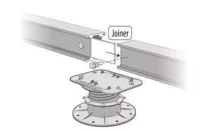
Where bearers need to be joined they need to be supported by a pedestal under the join, and then fixed with an aluminium joiner, centred between the two bearers on the inside the joist using 2 screws per joiner (for 90mm bearers use two joiners inside each bearer with one joiner in the upper position on one side of the bearer and in the lower position on the other side). The joiners are designed to be fixed between the lugs and the wall of the bearer, on the inside of the bearer.
In some instances where there is a cantilever at one end of the joist/bearer two joiners may be required (refer to deck plan).
Noggins fixed between joists can be used to support breaker boards and edge boards by making a “ladder joist”, rather than using 3 or 4 full length joists that are positioned close together.
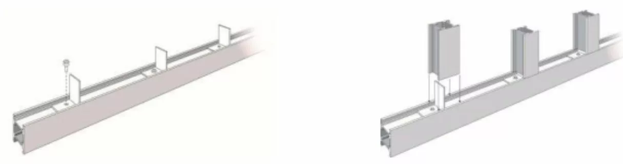
When using one bracket at each end of the noggin the brackets should be oriented so that they are on opposite sides of the noggin at each end.

Depending on the deck design two brackets per noggin may be required (refer to specific deck plan). The ladder joist or full length joists will need to be supported by pedestals or droppers that are spaced according to the span tables.
Where noggins or perimeter joists need to be attached to joists, they are fixed with a right-angle bracket.
The 25mm joist has a specific right-angle bracket with notches on one side of the bracket and a screw hole on the other side. This screw hole side of the bracket slides into place along one joist. The perpendicular joist slides over the other end of the bracket.
The screw hole side of the bracket is fixed in the recess on the outside wall of the joist. Care must be taken to make sure there is no swarf or other material caught between the back of the bracket and the joist wall so that the bracket sits flush against the joist wall and securely in the recess of the joist before it is screwed in place.
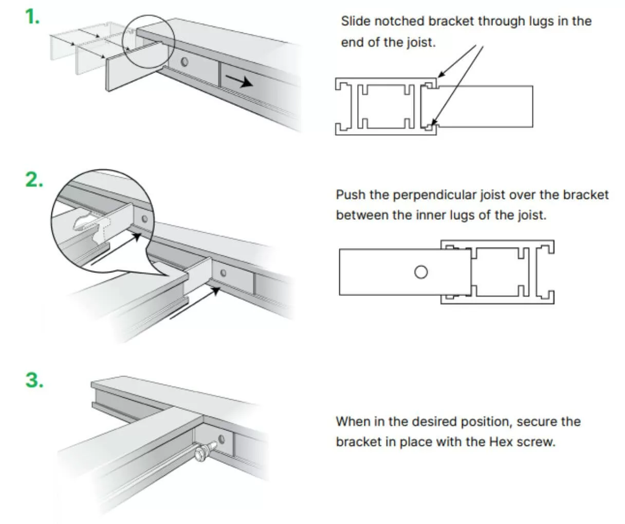
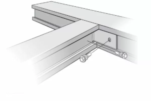
No screw is required for the side of the bracket that fits inside the joist if the perpendicular joist/noggin is fixed at the other end. If the perpendicular joist is not fixed at the other end, then a second screw should be fixed through the wall of the joist to secure the other side of the bracket within the joist.
The 50mm and the 90mm joist use the same right-angle bracket. The bracket has a screw hole on one side of the bracket, this side of the bracket is fixed in the recess on the outside wall of the joist. Care must be taken to make sure there is no swarf or other material caught between the back of the bracket and the joist wall so that the bracket sits flush against the joist wall and securely in the recess of the joist before it is screwed in place. The other side of the bracket is inserted inside the perpendicular joist between the side wall and the locating lug. The raised dimples on this face of the bracket are designed to go against the side wall of the joist to create a tight, interference fit.

Only 1 bracket per join is required to fix a 50mm joist to a 50mm joist for most residential deck loadings. Depending on the deck design two brackets may be required in some circumstances (refer to the specific deck plan for more details).
No screw is required for the side of the bracket that fits inside the joist if the perpendicular joist/noggin is fixed at the other end. If the perpendicular joist is not fixed at the other end, then a second screw should be fixed through the wall of the joist to secure the other side of the bracket within the joist.
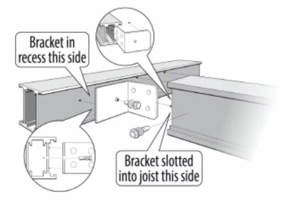
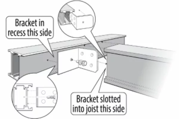
90mm joists attaching to other 90mm joists should use 2 right-angle brackets with one bracket in the upper position on one side of the joist and in the lower position on the other side.
The bracket end without the screw hole should be inserted into the joist/noggin before fixing either side of the bracket so that the position of the outside screw is marked correctly.
Droppers
Droppers are used on the outside edge of a deck in place of pedestals if the pedestal base position would mean that it protrudes past the deck edge when fascia boards or base boards are being fitted to the vertical underside edge of the deck or the deck butts against a wall.
If droppers are used to support a ladder joist or deck edge they will need to be spaced according to the span tables. If droppers are not used then secondary cantilevered members may be required to provide the necessary support for the deck edge.
The dropper is fixed under the deck joist or bearer using a “T” clip. The “T” clip is fixed in place with 2 screws and the dropper slides up over the bottom of the “T” bracket and is fixed in place with one screw.
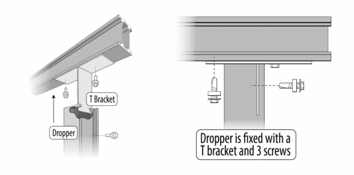
The dropper is also used as the frame to fix multiple fascia/base boards to.
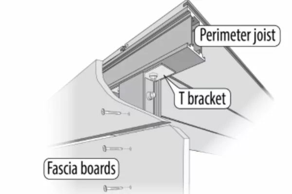
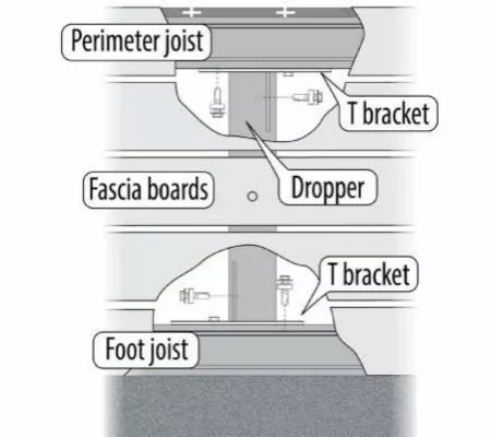
Droppers can also be used in place of a pedestal if the deck design requires no cantilever at the deck edge or to support cantilevers with a single back span configuration with no fixing/anchorage to the back span to prevent tip over.
A short section of joist can be used as a “foot” and attached to the bottom of the dropper if required. Droppers are fixed to the underside of the perimeter joist with a “T” bracket using 3 screws. The “foot” is also fixed to the dropper with a “T” bracket using 3 screws.
When the dropper is fixed to the end of a joist the “T” bracket is used and the protruding section of one side of the “T” is cut off. The “T” bracket is fixed using 3 screws. Care should be taken with the position of the screw that the dropper slides over so that the head of the screw fits within the hollow section of the dropper.
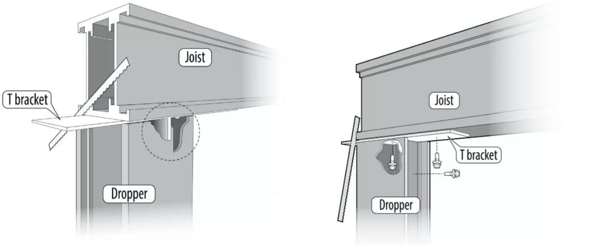
Fascias
The “T” bracket can be fixed to the underside of the perimeter joist with one screw to provide a support for fixing a single fascia board to the deck frame.
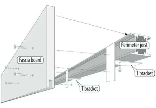
Steps
Please contact Futurewood for advice on how to build a frame for steps.
Balustrades
The Futurewood Aluminium Deck Frame System is not designed to support balustrades. Any balustrade design should be designed in conjunction with an engineer and would need to be supported from the ground up.